



Cylinder head assembly
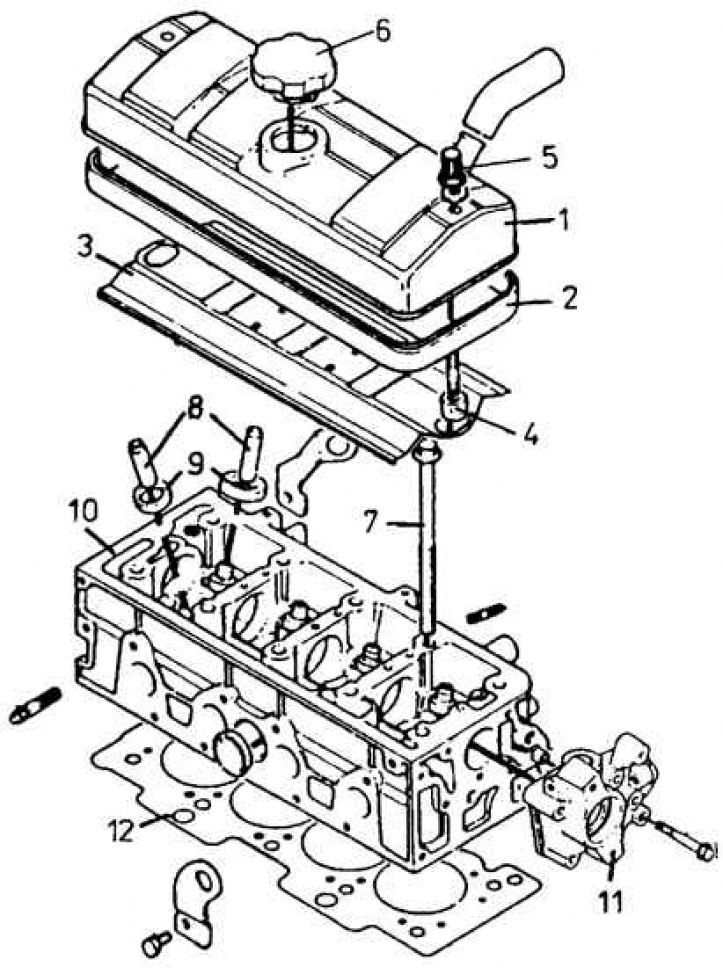
1 – valve cover, 2 – valve cover gasket, 3 – sheet casing (oil deflector), 4 – spacer sleeve, 5 – cover mounting bolt, 6 – oil filler plug, 7 – cylinder head bolt, 8 – valve guides, 9 – valve seats, 10 – cylinder head, 11 – ignition distributor bracket, 12 – cylinder head gasket
Timing unit with drive
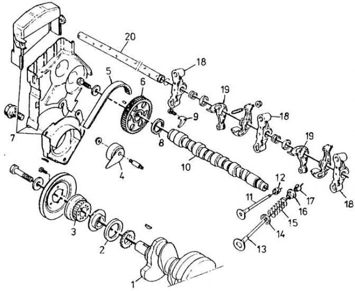
1 - Crankshaft, 2 - Front crankshaft seal, 3 - Crankshaft pulley, 4 - Timing belt tension roller, 5 - Timing belt, 6 - Camshaft pulley, 7 - Three-piece timing belt cover, 8 - Camshaft sealing ring, 9 - Camshaft mounting plate, 10 - Camshaft, 11 - Exhaust valve, 12 - Oil deflector cap, 13 - Inlet valve, 14 - Lower spring plate, 15 - Valve spring, 16 - Upper spring plate, 17 - Crackers, 18 - Valve lever axle brackets, 19 - Valve lever, 20 - Valve lever axle
1. Disconnect the ground cable from the battery.
2. Remove the air filter with pipes.
3. Drain the oil from the engine by unscrewing the drain plug in the oil pan.
4. Remove the flexible cooling system pipes connected to the cylinder head.
5. Disconnect all electrical wires from the cylinder head.
6. Disconnect the fuel lines and immediately seal them with appropriate plugs.
7. Unscrew the fuel pump mounting nuts and remove the pump.
8. Remove the accelerator pedal and starting device rods from the carburetor.
9. Remove the valve cover and take out the two spacer bushings and the sheet metal casing (oil deflector).
10. Piston 1st cylinder (counting from the flywheel) set to TDC position (both valves of the 1st cylinder are closed).
11. Engage 4th or 5th gear and apply the handbrake.
12. Disconnect the exhaust pipe from the exhaust manifold.
13. Unscrew the mounting bolts and remove the three-piece timing belt cover.
14. Loosen the tensioner roller and carefully remove the toothed belt, being careful not to bend it.
15. Unscrew the cylinder head bolts in several stages in order, from the middle outwards.
16. Remove all five valve lever axle brackets with levers and axle.
17. Tilt the cylinder head using two bent rods around one of the lower long edges of the head to separate it from the cylinder block.
18. Carefully remove the cylinder head gasket.
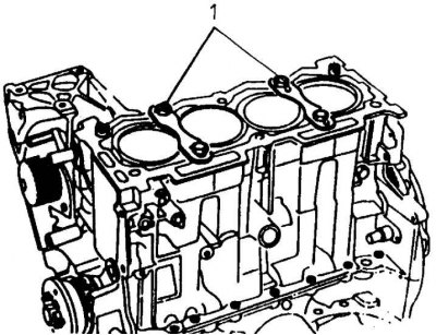
19. Attach the cylinder liners to the cylinder block using two special Peugeot plates (1) (fixture 0132 A1Z), screwing each plate with two M10 bolts 40 mm long.
Caution! The last three operations must be carried out very carefully so as not to accidentally lift the cylinder liners from their seats in the cylinder block, as this may lead to contamination of the mating surface and loss of sealing of the connection. In case of lifting the cylinder liners, the engine must be completely removed and then installed correctly.
20. Clean the upper surface of the cylinders from drops of oil and coolant.