



Table of contents: Removal 🠇 Assembly 🠇
Removal
Replacement of pistons and connecting rods can only be performed on a dismantled engine with the gearbox disconnected.
All pistons have two compression rings and one oil scraper ring. Piston rings have markings that must face upwards when the ring is installed (see illustration 22.0).
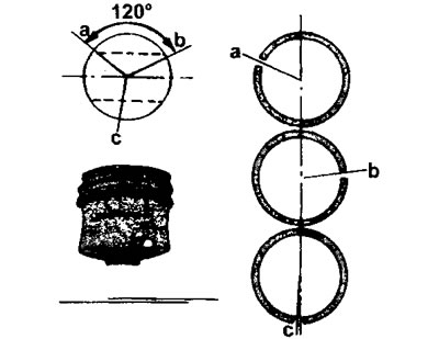
22.0 Piston rings and their location on the piston
a - upper compression ring
b - middle compression ring
c - lower (oil scraper) ring
In diesel engines, the cylinder pistons must protrude slightly above the cylinder block surface, so the cylinder head gaskets have different thicknesses.
No special tools are required to disassemble pistons and connecting rods. The connecting rod and piston group is the same for all engines. Pistons in different engine models differ only in size (see illustration 22.0a).
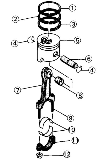
22.0a Connecting rod and piston group parts
1 - upper compression ring
2 - middle compression ring
3 - oil scraper ring
4 - piston pin retaining ring
5 - piston
6 - piston pin
7 - connecting rod
8 - connecting rod bushing
9 - connecting rod bolt
10 - connecting rod bearing shells
11 - connecting rod cover
12 - connecting rod cap fastening nut
1. Remove the piston rings in order using piston ring pliers. If these same rings are to be installed again, they should also be marked so that they are put back in their original places. If there are no pliers for installing piston rings, the latter are removed by placing metal plates under both ends of the rings.
2. Remove the thrust rings from the piston pin. To remove them, you need a small screwdriver, since the thrust rings do not have a protrusion. The thrust rings can also be removed using a hook by bending a piece of wire in the desired manner.
3. Place the piston with the connecting rod on a suitable support and knock out the piston pin. If the pin fits tightly, the piston and connecting rod can be heated in boiling water.
Caution! Disconnecting the piston and connecting rod is only necessary if the piston or connecting rod needs to be replaced.
4. Carefully inspect all parts. If there are any nicks, scratches or wear, they must be replaced.
Assembly
It is assumed that all parts have been checked and faulty ones have been replaced.
5. Check the connecting rods for twisting and deflection using a connecting rod testing machine. It is best to have this done in a workshop, as bent or even twisted connecting rods will result in the engine not operating properly.
6. Lubricate all parts with engine oil.
7. Arrange the pistons and connecting rods in the order of assembly, that is, the combustion chamber cavity in the piston crown and the protrusion for the connecting rod bearing shell should be located on the same side, as shown in (illustrations 22.7.)
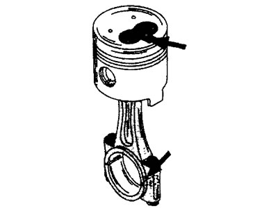
22.7 The combustion chamber cavity in the piston bottom and the protrusion for the connecting rod bearing shell must be located on the same side
8. Install the connecting rod and piston so that the connecting rod hole and the piston hole match. Install the piston pin retaining ring onto one side of the piston and ensure it fits snugly in the bore.
9. Insert the piston pin from the opposite side of the piston and drive it in until it stops. Use a plastic hammer if necessary. After this, install the second retaining ring.
10. Check the travel of the connecting rod on the piston pin. To do this, hold the piston in your hands and move the connecting rod in different directions. The connecting rod should move easily.
11. Install piston rings on the pistons (see illustration 22.0). Remember that the factory marking on the piston rings or the inscription "TOP" should be facing up, and the joint of the oil scraper piston ring should be located in line with the hole for the piston pin. The joints (locks) of the compression rings must be offset by 120° from the joint of the oil scraper ring (see illustration 22.0). Lubricate the piston rings generously with engine oil.
12. Lubricate the piston with engine oil and insert it into the corresponding cylinder bore. To compress the piston rings when installing the piston, a special mandrel is required. Place the compression mandrel around the piston so that the top edge of the piston protrudes 4-5 mm beyond the mandrel. This ensures uniform installation of the piston in the cylinder bore.
13. Install the connecting rod bearing caps (see the relevant chapter).