
Note. To properly adjust the timing belt tension, Peugeot/Citroen prescribes the use of a special electronic tool (belt tension measuring tool SEEM C.TRONIC, type 105). The following procedure is based on the use of this equipment (or equivalent alternative equipment calibrated to measure belt tension in SEEM units). Timing belt tension accuracy is very important, and if electronic equipment is not available, it is recommended that this work be done by a Peugeot/Citroen dealer or service station that has the appropriate equipment.
General information
1. The timing belt drives the camshaft, high pressure fuel pump and coolant pump from the toothed pulley at the end of the crankshaft. In addition, the belt drives the brake vacuum pump, not directly, but from the camshaft on the flywheel side. If the belt breaks or slips during operation, the pistons can come into contact with the valve heads, resulting in extensive damage resulting in costly repairs.
2. The timing belt should be replaced at prescribed intervals or sooner if it is contaminated with oil or makes noise when running (squeal/creak due to uneven wear).
3. If the timing belt is removed, it is recommended to check the condition of the coolant pump at the same time (check for signs of coolant leakage). This will help avoid the need to remove the belt at a later stage if the coolant pump fails.
4. There are two design options for the toothed pulley of the timing belt. Early engines use a camshaft pulley «floating» type, mounted on the hub of the toothed pulley with three bolts. The bolt holes are extended to allow some lateral movement of the toothed pulley to ensure accurate timing belt tension during installation. On later engines, the camshaft sprocket is fixed, but the crankshaft sprocket «floating». Lateral offset of the crankshaft sprocket is achieved by using a wider keyway. Both options use the same timing belt removal procedure, but different procedures must be used for installation.
Removing
5. Remove the crankshaft pulley as described in paragraph 5. Screw in and tighten the pulley mounting bolt so that the engine can be rotated in the following steps.
6. Remove the upper, intermediate and lower timing belt covers as described in paragraph 6.
7. Now it is necessary to identify the design type of the camshaft sprocket. On early engines, the toothed pulley and hub are a two-piece piece. The toothed pulley is attached to the hub with three bolts, and the hub is attached to the camshaft with one central bolt. On later engines, the toothed pulley and hub are a one-piece element, fixed to the camshaft only with a central bolt. When installing, proceed as described in the relevant subsections, according to the type of toothed pulley.
8. If you have not already done so, align the engine/camshaft assembly mounting holes as described in paragraph 3 and lock the crankshaft and camshaft sprocket. Do not attempt to crank the engine with the locking bars installed.
9. On early engines, loosen the three bolts securing the camshaft sprocket to the sprocket hub (pic. 8.9).
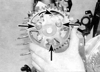
Pic. 8.9. Loosen bolts on early engines (marked with arrows) and turn the camshaft sprocket on the corresponding hub clockwise until it stops (engines 2.0 l)
10. Loosen the timing belt idler pulley bolt and insert a short 8.0mm square rod into the square hole on the face of the idler pulley. Alternatively, although access is limited, the square end of a socket extension with 1/4" shank can also be used. Use a rod and wrench to turn the pulley clockwise to release tension from the timing belt. Tighten the idler pulley bolt again to secure it in the released position.
Tip: The toothed pulley holding tool can be made from two strips of steel bolted together with a nut to form a fork structure. Bend the ends of the strips 90°to form ridges.
Advice. Make a toothed pulley release tool from a short steel plate. Drill two holes in the plate, matching the two holes in the pulley. Drill a third hole in the center large enough to fit the plate onto the pulley nut.
11. If the timing belt is to be used further, mark the direction of rotation on the belt with white paint or a marker (if the marking is not visible). Remove the belt from the toothed pulleys. Keep in mind that you should not turn the crankshaft with the belt removed.
12. Carefully check the timing belt for signs of uneven wear, delamination or oil contamination. Pay special attention to tooth cavities. Replace the belt if there is even the slightest doubt about its condition. If the engine is overhauled, replace the belt without fail, regardless of its external condition. The cost of a new belt is not comparable to the cost of repairing an engine in the event of a broken belt. If signs of oil contamination are found, locate the leak and repair the cause of the leak. Wash the engine in the area of the timing belt, as well as all relevant elements until all traces of oil are completely removed. Check that the tensioner and pulleys rotate freely without binding. If necessary, replace them as described in paragraph 9.
Installation
Two-piece camshaft pulley
13. Begin installation by checking that the engine/camshaft assembly mounting holes are still aligned as described in paragraph 3, and the crankshaft and camshaft sprocket hub are locked.
14. Slightly tighten the camshaft sprocket mounting bolts so that the camshaft sprocket can still move within the elongated grooves. Turn the toothed pulley clockwise to the end of the grooves.
15. Place the timing belt on the crankshaft sprocket with the arrow on the timing belt facing in the correct direction (according to belt rotation direction).
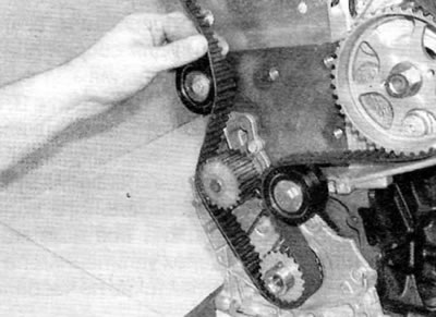
16. Hold the belt on the crankshaft sprocket and, keeping the lower section of the belt taut (between crankshaft and intermediate pulley), put the belt on the remaining toothed and smooth pulleys in the following sequence (pic. 8.16, a-d):
- A) intermediate pulley;
- b) high pressure fuel pump;
- V) camshaft;
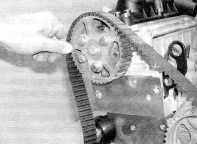
- G) coolant pump;
- d) tension pulley.
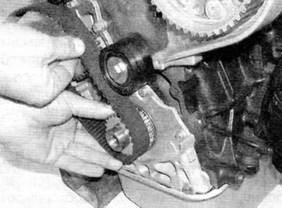
Pic. 8.16 a. Hold the timing belt on the crankshaft sprocket and pass it around the intermediate pulley...
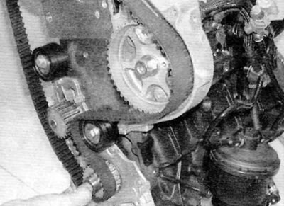
Pic. 8.16 b.... put on the gear pulley of the high pressure fuel pump...
Pic. 8.16, c.... camshaft pulley...
Pic. 8.16, d.... coolant pump gear pulley and idler pulley (engines 2.0 l)
17. Bring the sensor head of the electronic equipment for measuring the belt tension to the upper section of the timing belt, approximately in the middle between the camshaft and high pressure fuel pump toothed pulleys.
18. Loosen the idler pulley mounting bolt and use a square bar and wrench to turn the idler pulley counterclockwise until the gauge display shows an initial tension of 98±2 SEEM units (pic. 8.18, a, b). Hold the idler pulley in this position and tighten the bolt again.
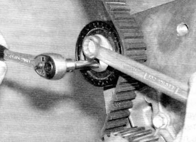
Pic. 8.18, a. Turn the idler pulley counterclockwise and then tighten the bolt...
Pic. 8.18b....when the measuring device shows the prescribed tension (engines 2.0 l)
19. Make sure that the camshaft sprocket bolts are not in the limit position in the corresponding grooves (if necessary, to check this, unscrew one of the bolts). If so, repeat the installation procedure. If everything is in order, tighten the three bolts securing the toothed pulley to the prescribed torque.
20. Remove the equipment for measuring belt tension and tools for blocking the crankshaft and camshaft sprocket hub.
21. Turn the crankshaft 8 full turns clockwise (viewed from the right side of the engine). Align the engine/camshaft assembly mounting holes again and insert the crankshaft locking tool.
22. Loosen the camshaft sprocket mounting bolts and install the camshaft sprocket hub locking tool.
23. Loosen the idler pulley mounting bolt again.
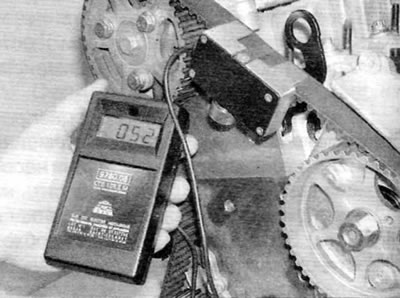
24. Position the belt tension measuring equipment at the top of the belt and turn the idler pulley to achieve a final setting of 54±2 SEEM. Hold the idler pulley in this position and tighten the bolt to the specified torque.
25. Tighten all bolts of fastening of a gear pulley of a camshaft the prescribed force.
26. Retract the sensing head of the belt tension measurement equipment, and then bring it back to the belt and check for an indication in the range of 54±3 SEEM units. Remove measuring equipment.
27. Remove the blocking tools, and then turn the crankshaft again two full turns clockwise. Align the engine/camshaft assembly mounting holes again and insert the crankshaft locking tool.
28. Verify that the camshaft sprocket hub locking tools can be inserted. If the tool cannot be inserted, check that the misalignment between the alignment slot in the toothed pulley hub and the mating hole in the cylinder head is less than 1.0 mm. If it exceeds, completely repeat the procedure for installing and tensioning the timing belt.
29. Install the lower, intermediate and upper timing belt covers as described in paragraph 6. Install the crankshaft pulley as described in paragraph 5.
Fixed camshaft sprocket
30. Verify that the engine/camshaft assembly mounting holes are still aligned as described in paragraph 3, and the crankshaft and camshaft sprocket are locked.
31. Turn the crankshaft sprocket counterclockwise until it stops, as far as the keyway allows. Lock the sprocket in this position by inserting a 2.0 mm rod into the groove to the left of the slotted key (pic. 8.31).
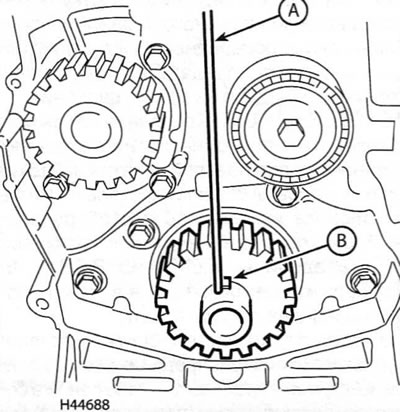
Pic. 8.31. Insert a rod with a diameter of 2 mm (A) into the groove on the left side of the segment key (IN) (engines 2.0 l)
32. Put the timing belt on the camshaft sprocket with the arrow on the timing belt pointing in the correct direction (according to belt rotation direction).
33. Hold the belt on the camshaft sprocket with a suitable clamp to prevent the belt from slipping off the teeth. Keeping the top section of the belt taut (between the toothed pulleys of the camshaft and the fuel pump), put the belt on the remaining toothed and smooth pulleys in the following sequence:
- A) high pressure fuel pump;
- b) intermediate pulley;) crankshaft;
- G) coolant pump;
- d) tension pulley.
34. Hold the clamp for fixing the timing belt on the camshaft sprocket and remove the rod from the keyway of the crankshaft sprocket.
35. Bring the sensor head of the electronic equipment for measuring belt tension to the upper section of the timing belt, approximately in the middle between the camshaft and fuel pump toothed pulleys.
36. Loosen the idler pulley mounting bolt and use a square bar and wrench to turn the idler pulley counterclockwise until the gauge display shows an initial tension of 98±2 SEEM. Hold the idler pulley in this position and tighten the bolt again.
37. If you have not already done so, screw in the bolt securing the crankshaft pulley (don't forget to install the washer) and tighten it to 70 Nm. Hold the crankshaft from turning with the flywheel ring gear locking tool described in the pulley removal procedure in paragraph 5. Do not attempt to use tools inserted into the engine/camshaft assembly mounting holes to prevent crankshaft rotation when tightening the bolt.
38. Remove the equipment for measuring belt tension, as well as the tool for locking the flywheel ring gear and tools inserted into the mounting holes for assembling the engine / valve timing.
39. Turn the crankshaft 8 full turns clockwise (viewed from the right side of the engine). Align the engine/camshaft assembly mounting holes again and insert the crankshaft and camshaft sprocket locking tools.
40. Install the flywheel ring gear locking tool and loosen the crankshaft pulley bolt.
41. Loosen the idler pulley mounting bolt again. Position the belt tension measuring equipment at the top of the belt and turn the idler pulley to achieve a final setting of 54±2 SEEM. Hold the idler pulley in this position and tighten the bolt to the specified torque.
42. Retract the sensor head of the belt tension measurement equipment, and then bring it back to the belt and check for an indication in the range of 54±3 SEEM units. If this is not the case, repeat the installation procedure completely. If the reading is correct, remove the measuring equipment.
43. Remove all locking tools, and then turn the crankshaft again two full turns clockwise. Align the engine/camshaft assembly mounting holes again and insert the crankshaft and camshaft sprocket locking tools. If inserting both tools fails, repeat the belt tensioning procedure completely.
44. If everything is in order, install the lower timing belt cover. Install the appropriate bolts and tighten them securely.
45. With the engine/camshaft assembly mounting holes aligned and the crankshaft and camshaft sprocket locking tools properly inserted, install the flywheel ring gear locking tool and install the crankshaft pulley bolt.
46. Install the crankshaft pulley on the end of the crankshaft.
47. Thoroughly clean the threads of the pulley bolt, and then apply a locking compound to the threads (Peugeot/Citroen recommends Loctite Frenetanch).
48. Screw the crankshaft pulley bolt (don't forget to install the washer). Tighten the bolt to the specified torque, and then tighten to the specified angle.
49. Remove the flywheel ring gear locking tool and the crankshaft and camshaft sprocket locking tools.
50. Install the intermediate and upper timing belt covers as described in paragraph 6, and then install and tension the accessory drive belt as described in chapter 1B.