



Note: This is a complex procedure, and you should carefully read the contents of this paragraph before starting. To facilitate installation, mark the installation position of the corresponding brackets and the routing of hoses, wires and cables before removal.
Note: On 2.0L engines, due to limited access, it is not possible to remove the cylinder head while the engine is on the vehicle unless significant additional disassembly is performed first*(for example, remove the front subframe and related components). Therefore, the description of the procedures for removing and installing the cylinder head is given in chapter 2D, taking into account that the engine assembly with the gearbox has been removed from the vehicle.
Removal
1. Disconnect the ground cable from the battery (see "Disconnecting the battery").
2. Drain the coolant from the cooling system as described in chapter 1B.
3. Remove the brake system vacuum pump as described in chapter 9.
4. Remove the timing belt as described in paragraph 7.
5. After removing the timing belt, unscrew the single bolt securing the right engine/gearbox support bracket to the cylinder head. Leave all bracket-to-cylinder block mounting bolts in place, then install the upper engine support bracket to the mount and securely tighten the associated nuts and bolts. The engine and transmission assembly will need to be securely supported throughout the following procedure.
6. If the cylinder head needs to be overhauled, remove the camshaft timing pulley and camshaft (see paragraphs 9 and 11).
7. Follow these steps (see chapter 4B):
- a) remove the air filter housing;
- b) remove the intake and exhaust manifolds;
- c) disconnect the return fuel hose from the outer injector and remove it;
- d) unscrew the union nuts and disconnect the fuel lines from the fuel injectors and high-pressure fuel pump. Remove the pipelines;
- d) If the cylinder head is subject to major repair, remove the injectors.
8. Remove the cylinder head cover as described in paragraph 4.
9. Remove the fuel filter as described in chapter 1B.
10. Unscrew the bolt and remove the plastic filter housing together with the sealing ring (figure 13.10). Discard the sealing ring; when installing, you should use a new one.
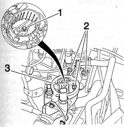
Figure 13.10. Remove the bolt (1) and the fuel filter housing, then remove the three bolts (2) and the filter/thermostat housing (3) from the cylinder head (1.9 L engines)
11. Remove three bolts (paying attention to the installation position of the sealing washer), used to secure the fuel filter/thermostat housing to the front of the cylinder head. Disconnect the coolant hose connecting the housing to the coolant line, and then separate the housing from the cylinder head. Remove the housing gasket and discard it; when installing, you should use a new one.
12. Loosen the nut and disconnect the power wire from the corresponding glow plug. Remove the washers.
13. Remove the bolt securing the coolant line to the left end of the cylinder head.
14. Ensure that the electrical wiring and hoses are released from all appropriate clamps or guides on the cylinder head and positioned out of the way.
15. Working in the reverse order to that shown in the figure 13.32, gradually loosen the 10 cylinder head mounting bolts, performing half a turn at a time, until all the bolts can be unscrewed by hand.
16. After unscrewing all the cylinder head mounting bolts, separate the cylinder head from the cylinder block and the mounting pin by rocking it. The special Peugeot/Citroen tool for this procedure consists of two metal rods with the ends bent at right angles. Do not pry with improvised levers inserted between the mating surfaces of the head and cylinder block, as this may result in damage to the gasket surfaces. Remove the cylinder head; if possible, use outside help.
17. Remove the gasket from the top surface of the block, paying attention to the mounting pin. If the dowel pin is not secured, remove it and store it in a safe place along with the head. Don't throw away the pad; it will be required for identification purposes (see paragraphs 22-25).
18. If the cylinder head must be disassembled for major repair, remove the camshaft and tappets as described in paragraph 11, and then refer to chapter 2D.
Preparing for installation
19. Before installing the cylinder head, thoroughly clean the mating surfaces of the cylinder head and cylinder block. To remove any remaining gasket material and carbon deposits, use a hard plastic or wooden scraper. Clean the piston crowns. Be extremely careful when cleaning, as the soft aluminum alloy is easily damaged. Prevent carbon deposits from entering the lubrication and coolant passages. This is especially important for the lubrication system, as carbon deposits can block the supply of oil to engine components. Cover the cooling and lubrication passages and bolt holes in the cylinder block/crankcase with masking tape and paper. To prevent the removed carbon deposits from getting into the gaps between the pistons and the cylinder walls, introduce a small amount of grease into the gap. After cleaning each piston, take a small brush and remove all traces of grease and carbon deposits from the gap, then wipe everything with a clean cloth. Also clean all pistons.
20. Check the mating surfaces of the cylinder block and cylinder head for scoring, deep scratches and other damage. If they are minor, carefully remove them with a file. But if they are large, the only alternative to replacement may be mechanical treatment.
21. If there is a suspicion of deformation of the mating surface of the cylinder head (under the gasket), check this surface with a ruler. If necessary, please contact chapter 2D.
22. When purchasing a new cylinder head gasket, care should be taken to ensure that the gasket is of the correct thickness. Six different gasket thicknesses are available to precisely define the distance between the cylinder head mating surface and the piston crowns. The thickness of the gasket can be determined by carefully examining the protrusion on the gasket located in front of cylinder No. 1 (figure 13.22). The ledge may have from 3 to 7 holes. The first two holes (group of holes A) show the engine type (DW8), they are present on all gaskets and have no real meaning. But the last group, which includes from 1 to 5 holes (group of holes B), shows the thickness of the gasket as described below.
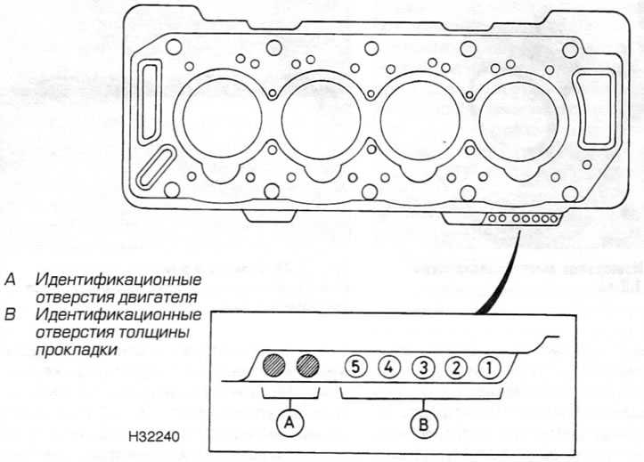
Figure 13.22. Identification holes on the cylinder head gasket (1.9 L engines)
| Number of holes | Gasket thickness |
| (hole positions) | (in the installed position) |
| 1(1) | 1.26 mm |
| 2(1 and 2) | 1.30 mm |
| 3(1,2 and 3) | 1.34 mm |
| 4(1,2,3 and 4) | 1.38 mm |
| 5(1,2,3,4 and 5) | 1.42 mm |
| 2(1 and 5) | 1.46 mm |
The correct shim thickness required is selected by measuring the piston protrusion as described below.
23. Ensure the flywheel is properly locked in the position where pistons #1 and #4 are exactly at TDC. Securely attach the dial indicator to the cylinder block so that its plunger can easily rotate from the mating surface of the cylinder block to the piston crown and back. Zero the indicator scale by moving the plunger tip to the mating surface of the cylinder block, and then carefully move the indicator plunger to the bottom of piston No. 1 and measure its protrusion (figure 13.23). Take measurements at the front and back of the piston crown and calculate the average value from the two measurements. This will be the piston protrusion. Repeat this procedure on piston #4.
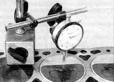
Figure 13.23. Measuring piston protrusion (1.9 L engines)
24. Remove the locking tool, then rotate the crankshaft 1/2 turn (180°) clockwise to bring pistons #2 and #3 to TDC. Make sure the crankshaft is correctly aligned, then measure the protrusion of pistons #2 and #3. Once all four pistons have been measured, rotate the crankshaft another 1/2 turn (180°) clockwise to bring pistons #1 and #4 back to TDC, then lock the flywheel again.
25. Using the largest protrusion value of the four pistons, select the correct shim thickness required using the table below:
| Piston protrusion | Required gasket thickness |
| 0.510 - 0.549 mm | 1.26 mm |
| 0.550 - 0.589 mm | 1.30 mm |
| 0.590 - 0.629 mm | 1.34 mm |
| 0.630 - 0.669 mm | 1.38 mm |
| 0.670 - 0.709 mm | 1.42 mm |
| 0.710 - 0.750 mm | 1.46 mm |
26. Carefully inspect the cylinder head bolts for signs of thread or head damage and for signs of corrosion. If the bolts are in good condition, measure the length of each bolt from the back of the head to the end of the guide (non-threaded) section at the base of the bolt shaft (figure 13.26). Bolts may be reused if their length does not exceed 125.5 mm. Keep in mind that if a bolt is reworked to accommodate the gasket (see item 28), a new bolt will be required for final cylinder head installation.
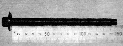
Figure 13.26. Measure the length of each bolt from the back of the head to the end of the bolt (1.9 L engines)
Note: Due to the stresses that occur in the cylinder head bolts, it is strongly recommended that they be replaced, regardless of their external condition.
Installation
27. Turn the crankshaft clockwise (when viewed from the timing belt side) so that pistons No. 1 and 4 pass the bottom dead center (BDC) and begin to rise, and then position them in the middle of the upward stroke. Pistons #2 and #3 will also be in the middle of their stroke, but on a downward stroke.
28. Wipe clean the mating surfaces of the cylinder head and block. Properly install the correct gasket onto the cylinder block with the identification holes facing the front of the engine and near cylinder #1 (on the flywheel side). Make sure the dowel pin is in place: at the end of the cylinder block where the timing belt is located. Please note that due to the presence of only one dowel pin, the gasket may become displaced when installing the cylinder head (due to the engine tilt), especially when the cylinder head is installed on the engine without removing it from the vehicle. In the worst case, pistons and/or valves can hit the gasket, causing engine damage. To avoid this problem, cut the head off the "old" cylinder head bolt and cut a slot in the end of the bolt so that the bolt can be turned with a screwdriver. Thread a bolt into one of the bolt holes on the flywheel end of the cylinder block, then position the gasket using the bolt and dowel pin as a guide. This will help hold the gasket in place when installing the cylinder head.
29. With the help of an assistant, carefully lower the cylinder head onto the block, using the locating pin as a guide.
30. Apply a small amount of grease to the threads and to the back of the cylinder head bolt heads. Peugeot/Citroen recommends using Molykote G Rapid Plus grease (can be purchased from a dealer).
31. Carefully insert each bolt into its corresponding hole (don't let them fall) and screw them in with just the force of your hand.
32. Working gradually and in the prescribed sequence, using a torque wrench and a suitable socket, tighten the cylinder head bolts to the prescribed torque as per stage 1 (figure 13.32).
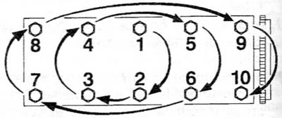
Figure 13.32. Cylinder head bolt tightening sequence (1.9 L engines)
33. After tightening all bolts according to Step 1, working again in the same sequence, tighten each bolt to the specified torque according to Step 2.
34. Finally, using a socket head and extension, tighten the bolts to the specified angle as per step 3. To ensure accuracy, it is recommended to use a protractor at this stage of tightening. If a protractor is not available, mark the relative positions of the bolt head and cylinder head with white paint before tightening. These marks can then be used to check that the bolt is turned to the correct angle during tightening.
35. If necessary, install the camshaft and/or camshaft timing pulley (see paragraphs 9 and 11). If the cylinder head has been rebuilt, check the valve clearances before proceeding with the following steps.
36. Install reliable supports (or use a lifting device) under the engine/transmission, and then remove the support bracket from the right engine/transmission mount. Screw in the bracket mounting bolt to the cylinder head and tighten it to the specified torque.
37. Install the timing belt as described in paragraph 7.
38. Screw in the coolant line mounting bolt and securely connect the glow plug electrical connector.
39. Clean and dry the mating surfaces and install the fuel filter/thermostat housing onto the cylinder head, using a new gasket. Screw in the housing mounting bolts (install the sealing washer onto the bolt located on the inside of the filter housing) and tighten them to the specified torque. Securely connect the coolant hose to the body.
40. Install a new sealing ring onto the base of the plastic fuel filter housing and install the housing, tightening the corresponding bolt to the specified torque.
41. Install the cylinder head cover (see paragraph 4).
(Source available here www.PEUGEOTBOOK.ru)
42. Follow these steps (see chapter 4B):
- a) install the injectors (if removed);
- b) Install the fuel lines connecting the high-pressure fuel pump to the injectors and connect the return hoses to the injectors;
- c) install the manifolds and air filter housing.
43. Install the brake system vacuum pump as described in chapter 9.
44. Install a new fuel filter and fill the cooling system as described in chapter 1B.
45. Connect the battery, then fill and bleed the fuel system as described in chapter 4B.