
Note. Due to limited access, it is not possible to remove the cylinder head while the engine is on the vehicle unless extensive additional disassembly is first performed (e.g. remove the front subframe and related components). Below is a description of the procedures for removing and installing the cylinder head, taking into account that the engine and transmission assembly has been removed from the vehicle.
Removing
1. Remove the engine/gearbox assembly as described in paragraph 4.
2. Remove the timing belt as described in chapter 2B.
3. Perform the following steps as described in chapter 4B:
- A) Remove the exhaust manifold and turbocharger.
- b) Remove the intake manifold.
- V) Remove the fuel rail.
4. Turn out the three bolts and remove the upper bracket of the right engine support from the engine support bracket. Turn out bolts of fastening of a basic arm of the engine to a head and the block of cylinders and remove an arm.
5. Remove the brake vacuum pump as described in chapter 9.
6. Disconnect the electrical connectors and disconnect the coolant hoses on the thermostat housing at the left end of the cylinder head.
7. Turn out bolts and release directing plait of electroconducting from a clamp on the thermostat case.
8. Turn away nuts, turn out bolts and remove the left basic arm of directing plait of electroconducting of fuel atomizers.
9. Turn out a bolt and release a tube of the rod indicator of level of oil from a clip on a head of cylinders.
10. Move aside all adjacent elements, then turn out three bolts and turn away two nuts of fastening of the case of the thermostat to a head of cylinders. Remove the hose and wiring support bracket, and then remove the thermostat housing. Remove the body gasket.
11. Remove the cylinder head cover as described in chapter 2B.
12. Gradually loosen the cylinder head bolts in the reverse order shown (pic. 5.29).
13. When all bolts are released, turn out them completely and remove from a head of cylinders.
14. Separate a head of cylinders from the block of cylinders and adjusting pins, swinging it. The Peugeot/Citroen special tool for this procedure consists of two metal rods with ends bent at right angles (pic. 5.14). Do not pry with makeshift levers inserted between the mating surfaces of the head and cylinder block, as this may damage the surfaces under the gasket.
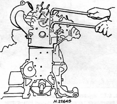
Pic. 5.14. Release the cylinder head using the rods, the ends of which are bent at right angles
15. Remove the cylinder head from the block and remove the gasket.
Preparing for installation
16. Before installation of a head of cylinders carefully clear interfaced surfaces of a head of cylinders and the block of cylinders. Peugeot/Citroen recommends the use of a special cleaner for this purpose, but an acceptable result in removing all traces of gasket and carbon deposits can be achieved with a hard plastic or wooden scraper. The same method can be used to clean piston crowns. Be very careful not to scratch or otherwise damage the mating surfaces of the cylinder block and cylinder head when cleaning, as the aluminum alloy can be easily damaged. Make sure that deposits do not get into the lubrication channels and channels of the cooling system. This is especially important for the lubrication system, as deposits can block the oil supply to engine components. Use tape and paper to cover the oil passages, coolant passages and bolt holes in the cylinder block. In order to prevent the removed deposits from getting into the gaps between the pistons and the cylinder walls, put a little grease into the gap. After cleaning each piston, take a small brush and remove all traces of grease and carbon from the gap, then wipe everything with a clean rag.
17. Check the mating surfaces of the engine block and cylinder head for burrs, deep scratches and other damage. If they are minor, they can be carefully removed with a file. If they are large, the only alternative to replacement is machining. If deformation of the cylinder head mating surface is suspected (under the gasket), check this surface with a ruler. If necessary, contact paragraph 8.
18. Thoroughly clean the threads of the holes for the cylinder head bolts in the cylinder block. Make sure the bolts turn freely and all traces of oil and water are removed from each bolt hole.
Gasket selection
19. Rotate the crankshaft so that pistons No. 1 and 4 are at TDC. Install a dial indicator on the cylinder block and zero the scale by bringing the indicator plunger to the mating surface of the block. Move the plunger to the edge of the No. 1 piston, and then slowly rotate the crankshaft back and forth to bring the piston past TDC while observing the highest reading on the indicator scale. Record this reading.
20. Repeat this procedure on piston No. 4, and then rotate the crankshaft a half turn (180°) and repeat the procedure on pistons No. 2 and 3 (pic. 5.20).
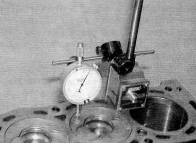
Pic. 5.20. Measure piston protrusion with a dial gauge
21. If no dial gauge is available, piston protrusion can be measured with a ruler and «fan» feeler gauge or with a caliper. However, this is less accurate and therefore not recommended.
22. Record the largest piston protrusion and use it to select the correct cylinder head gasket from the following table. Notches on the side of the gasket are used to identify the thickness.
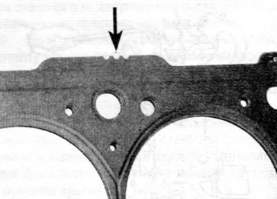
Pic. 5.22. Cylinder head gasket thickness identification grooves (marked with arrows)
| Piston protrusion | Gasket identification |
| 0.470...0.605 mm | 7 groove |
| 0.605...0.655 mm | 9 groove |
| 0.655...0.705 mm | 3 slots |
| 0.705...0.755 mm | 4 slots |
| 0.755...0.830 mm | 5 slots |
Inspection of cylinder head bolts
23. Carefully inspect the cylinder head bolts for signs of thread or head damage and for signs of corrosion. If the bolts are in satisfactory condition, measure the length of each bolt from the underside of the head to the end of the bolt. Bolts can be reused if their length does not exceed 133.3 mm. Note. Given the stresses that occur in the cylinder head bolts, it is strongly recommended to replace them, regardless of their external condition.
Installation
24. Turn the crankshaft clockwise (viewed from the timing belt side) until pistons 1 and 4 are past bottom dead center (NMT) and began to rise, and then position them in the middle of the upward stroke. Pistons #2 and #3 will also be in the middle of their stroke, but downstroke.
25. Verify that the dowel pins are in place. Correctly install the proper gasket on the cylinder block with the identification slots facing the side of the engine where the fuel pump is located.
26. Lower the cylinder head onto the cylinder block.
27. Apply some lubricant to the threads and to the back of the heads of the cylinder head bolts. Peugeot/Citroen recommends Molykote G Rapid Plus (can be purchased from a dealer).
28. Carefully insert each bolt into the appropriate hole (don't let them fall) and screw them in by hand only.
29. Working gradually and in the prescribed sequence, using a torque wrench and a suitable socket, tighten the cylinder head bolts to the prescribed torque according to stage 1 (pic. 5.29).
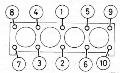
Pic. 5.29. Cylinder head bolt tightening sequence
30. After tightening all the bolts according to step 1, working again in the same sequence, tighten each bolt to the prescribed torque according to step 2. Finally, tighten the bolts to the specified angle according to step 3. To ensure accuracy, it is recommended to use a goniometer at this stage of tightening.
31. Install the cylinder head cover as described in chapter 2B.
32. Clean the mating surface of the cylinder head and thermostat housing, and then install the housing using a new gasket. Install the support bracket for hoses and wires, tighten the nuts and screw the bolts of the thermostat housing. Tighten nuts and bolts securely.
33. Screw in and tighten the bolt of the oil level indicator tube.
34. Install the wiring harness guide support bracket.
35. Connect the coolant hoses to the thermostat housing.
36. Install the timing belt as described in chapter 2B.
37. Install the fuel rail, intake manifold, exhaust manifold and turbocharger as described in chapter 4B.
38. Install the brake vacuum pump as described in chapter 9.
39. Install the elements of the right engine mount (see chapter 2B).
40. Install the engine/gearbox assembly as described in paragraph 4.