
2. Front cylinder head. Disconnect the guide tube 1 of the dipstick (see illustration).
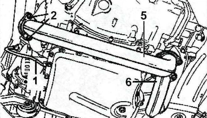
4.2 Disconnect the guide tube 1 of the dipstick
3. Unscrew the bolts 2, with which the exhaust pipe 5 is attached to the exhaust manifold on the front cylinder head (see illustration 4.2).
4. Unscrew the two bolts 3 that secure the generator support bracket (see illustration).
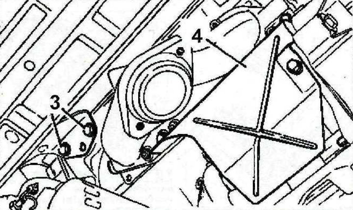
4.4 Unscrew the two bolts 3 that secure the generator support bracket
5. Remove heat shield 4 (see illustration 4.4).
6. Disconnect the intake pipes 5 and 6 from the exhaust manifold of the rear cylinder head by unscrewing the mounting bolts (see illustration 4.2).
7. Unscrew the lambda probe 7 from the connecting pipe 8 of the catalyst of the exhaust system of the front cylinder head, disconnect both exhaust pipes, as well as the catalyst (see illustration).
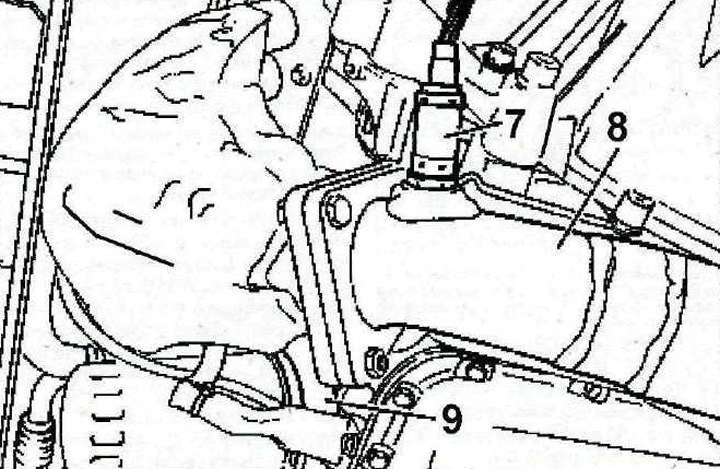
4.7 Unscrew the lambda probe 7 from the connecting pipe 8 of the exhaust system of the front cylinder head of the catalyst and disconnect both exhaust pipes
8. Disconnect the oil filter and remove the oil cooler 9 without disconnecting the oil lines from it (see illustration 4.7).
9. Unscrew the lambda probe from the connecting pipe of the catalyst 10 of the exhaust system of the rear cylinder head and disconnect the catalyst (see illustration).
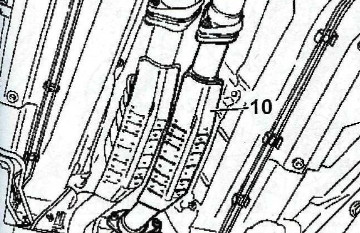
4.9 Unscrew the lambda probe from the connecting pipe of the catalytic converter 10 of the exhaust system of the rear cylinder head and disconnect the catalytic converter
10. Disconnect from a front head of the block of cylinders a hose 11 and an arm 12 (see illustration).
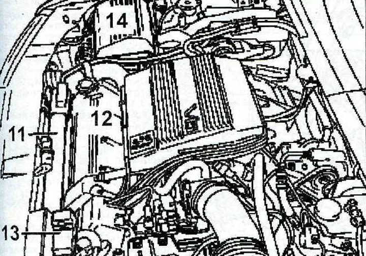
4.10 Disconnect hose 11 and bracket 12 from the front cylinder head
11. Remove the battery 13 and its tray (see illustration 4.10).
12. Unscrew the mounting bolts and move the engine control unit 14 to the side (see illustration 4.10).
13. Unscrew the mounting bolts and remove the power steering pump, as well as the power steering reservoir.
14. Unscrew the mounting bolts and move the air conditioning compressor to the side without disconnecting the hoses or refrigerant circulation pipes from it.
Attention! All work concerning the opening of the refrigerant circulation system should be entrusted to a specialized workshop.
15. Remove the intake manifold 15 and pipeline 16 from the rear cylinder head by unscrewing the mounting bolts (see arrows in illustration).
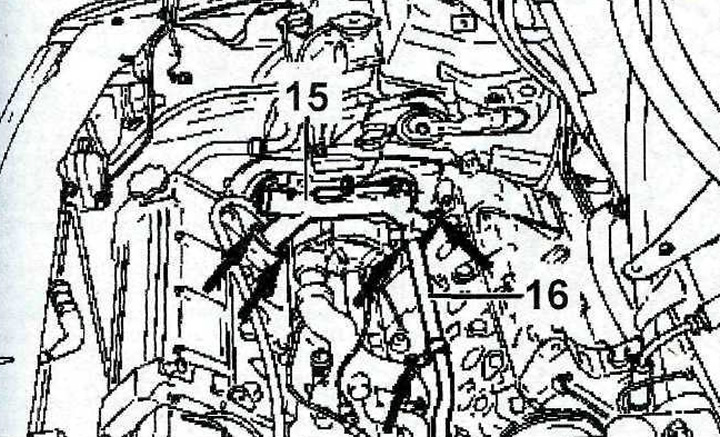
4.15 Remove the intake manifold 15 and pipeline 16 from the rear cylinder head by unscrewing the mounting bolts (see arrows)
16. Remove the cover from the front cylinder head.
17. Loosen the tension of the balance shaft drive chain by compressing the tension spring with a suitable tool, such as 0164-F, which is used in specialized workshops, see the relevant chapter.
18. Unscrew the bolt 17 and the sprocket mounting bolt 18 and remove the sprockets 18 and 19 together with the balancing shaft drive chain (see illustration).
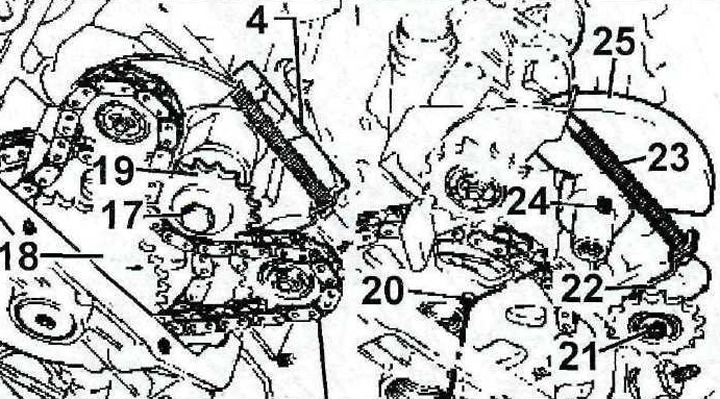
4.18 Unscrew the bolt 17 and the sprocket mounting bolt 18 and remove the sprockets 18 and 19 together with the balancing shaft drive chain
4 - a device for loosening the tension of the balancing shaft chain
19. Turn the crankshaft in the direction of engine travel until the hole on the drive shaft sprocket is aligned with the hole on the rear cover of the gas distribution mechanism and fix the drive shaft by inserting a thrust roller 20 into the holes (see illustration 4.18).
20. Remove tool 4 to loosen the balance shaft chain tension, balance shaft 21, chain tensioner 22 and tensioner spring 23 (see illustration 4.18).
21. Remove the balancer 25 and remove the key 24 (see illustration 4.18).
22. Install special plate 5a, fixing it with two bolts 26, tightening them by hand, and then fix the chain on the camshaft sprocket with stop 5b and plate 5c (see illustration). Then tighten bolts 26.
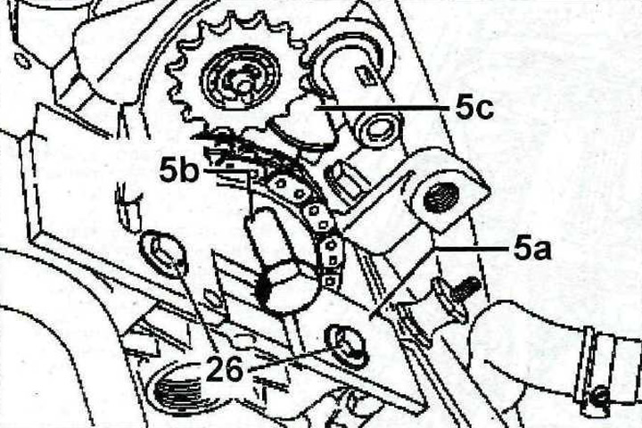
4.22 Install the special plate 5a, securing it with two bolts 26, and then fix the chain on the camshaft sprocket with stop 56 and plate 5c
23. Disconnect the upper hose from the thermostat housing.
24. Unscrew the bolts 27, with which the protective cover of the timing gear is attached to the cylinder head (see illustration).
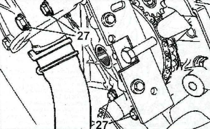
4.24 Unscrew the bolts 27, with which the protective cover of the timing gear is attached to the cylinder head
25. Remove the cover 28. gasket 28 of the ignition distributor and remove the slider 30 (see illustration)
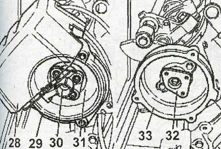
4.25 Remove cover 28, gasket 28 of the ignition distributor and remove slider 30
26. Remove gasket 31, flange 32 and body 33 of the ignition distributor (see illustration 4.25).
27. Unscrew bolts of fastening of a forward head of the block of cylinders, acting in the specified sequence (see illustration).
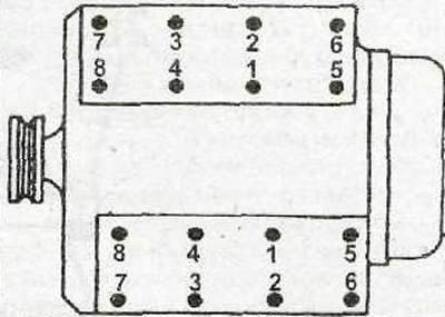
4.27 The sequence of unscrewing the cylinder head bolts
28. Remove the stop 35, which prevents the axial runout of the camshaft, by unscrewing the bolt 34 (see illustration). After removing the stop, bolt 34 must be screwed in again.
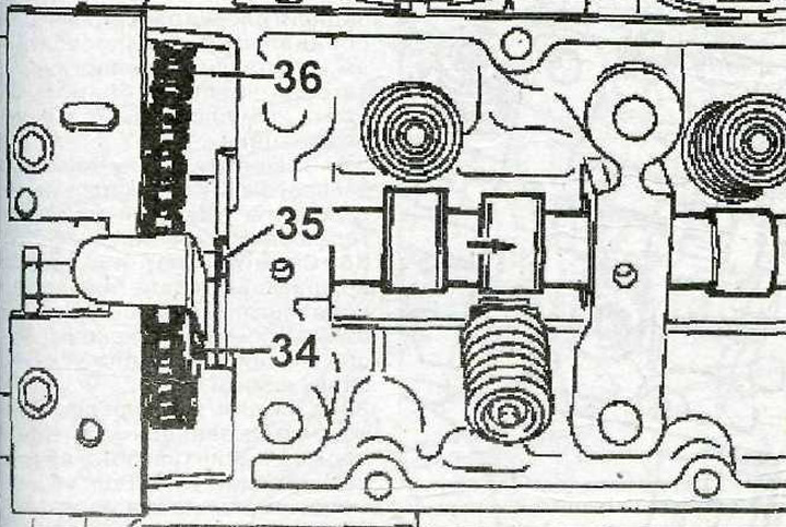
4.28 Remove stop 35 preventing axial runout of the camshaft by unscrewing bolt 34
29. Remove sprocket 36 from the camshaft along with the chain (see illustration 4.28)
Attention! To remove the rear cylinder head, the right engine mount must be removed.
30. Unscrew the bolt 37 of the bracket of the right engine mount (see illustration).
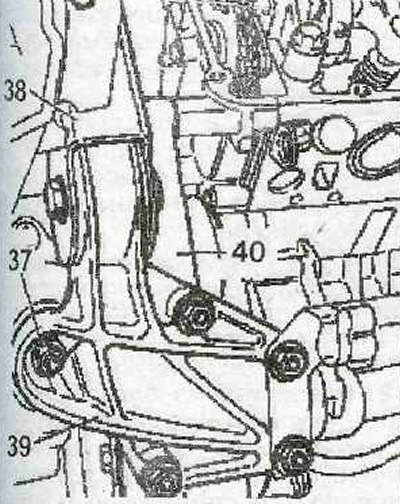
4.30 unscrew the bolt 37 of the bracket of the right engine mount
31. Place a garage jack under the engine with a block of wood on top of the jack and raise the right side of the engine as far as possible to remove the right suspension mount.
32. Remove the right support 40 of the engine by disconnecting the brackets 39 and 40 (see illustration 4.30).
33. Remove the cover from the rear cylinder head if it has not been removed before.
34. Unscrew the bolts 41, with which the protective cover of the gas distribution mechanism is attached to the cylinder head, and also remove the plug 42, which closes the bolt of the camshaft sprocket (see illustration).
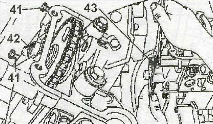
4.34 Unscrew the bolts 41, with which the protective cover of the gas distribution mechanism is attached to the cylinder head, and also remove the plug 42
35. Unscrew the threaded pin 43 using two M9x125 nuts (see illustration 4.34).
36. Fix the chain on the camshaft sprocket of the rear cylinder head with a special tool consisting of plate 2a, which is fastened with bolts 43, bolt 2b and plate 2c (see illustration).

4.36 Fix the chain on the camshaft sprocket of the rear cylinder head with a special tool consisting of plate 2a, bolt 2b and plate 2c
37. Unscrew bolts of fastening of a back head to the block of cylinders, operating in the specified sequence (see illustration 4.27).
38. Remove the stop 45, which prevents the axial runout of the camshaft, by unscrewing the bolt 44 (see illustration). After removing the stop, bolt 34 must be screwed in again.
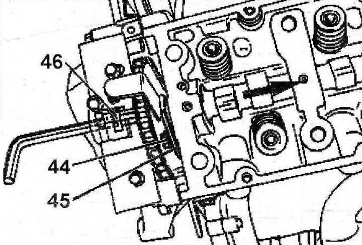
4.38 Remove stop 45 preventing camshaft axial runout by unscrewing bolt 44
39. Remove the sprocket together with the chain from the camshaft by unscrewing the bolt 46 (see illustration 4.38). It is recommended to screw bolt 46 into the hole on the shaft after removing the sprocket
40. Loosen the fit of the heads on the cylinder blocks, and then remove the heads using the special levers [9], as well as the gaskets (see illustration).
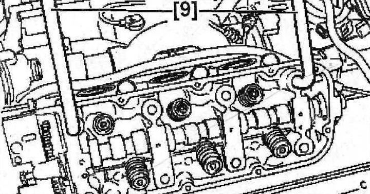
4.40 Loosen the fit of the heads on the cylinder blocks, and then remove the heads using the special levers [9]
41. Remove from both heads, if necessary, bearing housings, rocker axles, pushers, camshafts, and valves.
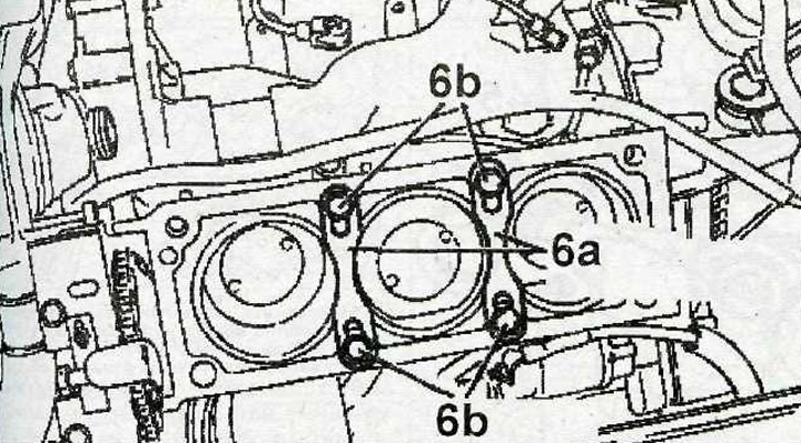
4.41 Fix the cylinder liners with special clamps 6a
Attention! It is recommended to fix the cylinder liners on the blocks with special clamps 6a. screwing in the bolts 6b to prevent the sleeves from coming out (see illustration).
42. Remove the bushings from the cylinder block 49, with which the head is centered on the block. To remove the bushings, use a special tool 1, for example, 0134L (see illustration).
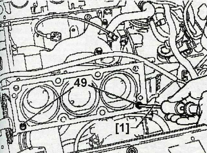
4.42 Remove bushings 49 from the cylinder block, with which the head is centered on the block
43. Clean the mating surfaces of the heads and cylinder blocks, as well as the threads of the holes for the head bolts.
44. Check the cylinder head for distortion and warping (see illustration). Check the curvature with a steel ruler and a measuring template at several points. Permissible LX deformation C should not exceed 0.05 mm.
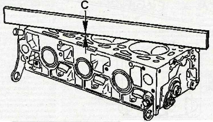
4.44 Check the cylinder head for distortion
Attention. Modification of cylinder heads is not allowed.
45. Check piston protrusion. The protrusion of the pistons should be within 0.05-0.12 mm. The permissible protrusion difference between two adjacent cylinders must not exceed 0.04 mm.