
Attention! If one of the components of the timing drive is worn or damaged, it is recommended to change not only this part, but also install new chains, sprockets, guides and chain tensioners.
To replace the timing drive parts, the engine must be dismantled.
Attention! In order to correctly install the sprockets and lay the drive chains during installation, it is recommended to mark their installation position before removal.
1. Unscrew bolts of fastening of covers 1 and 2 of heads of both blocks of cylinders and remove covers (see illustration).
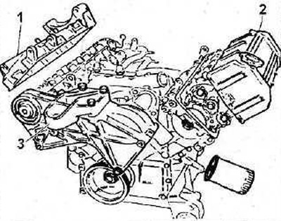
3.1. Unscrew bolts of fastening of covers 1 and 2 of heads of blocks of cylinders and remove covers.
2. Remove the thermostat housing 3 by disconnecting the hoses from its nozzles and remove the auxiliary drive belt (see illustration 3.1).
3. Release the water pump wires from the holders, disconnect the lower radiator hose 2 from the pump, and then unscrew the water pump mounting bolts and move it away from the work site (see illustration).
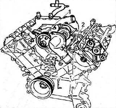
3.3 Unscrew the water pump mounting bolts and move it away from the work site
2 - branch pipe of the lower radiator hose
4. Unscrew the nut 1 fastening the pulley 2 of the auxiliary drive to the crankshaft and remove the pulley (see illustration).
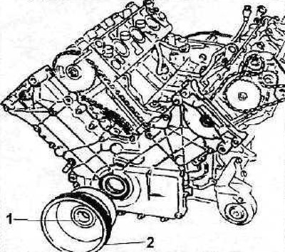
3.4 Unscrew the nut 1 securing the pulley 2 of the auxiliary drive to the crankshaft and remove the pulley
Attention! The pulley is held on the crankshaft by a key, which, after removing the pulley, must be removed from the groove to prevent loss. It is recommended to remove the pulley from the shaft with a suitable puller.
5. Remove the crankshaft front oil seal from the timing cover (see illustration 3.6).
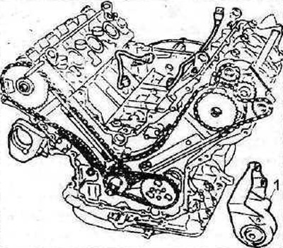
6. Unscrew the bolts 1 that secure the protective cover of the timing gear drive and remove the cover (see illustration 3.6).
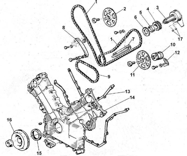
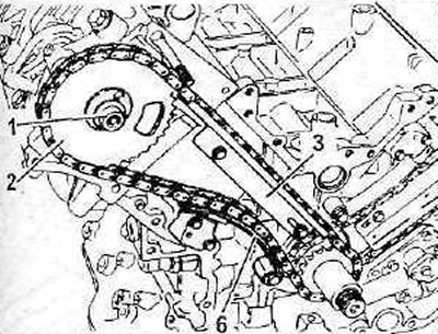
3.6 Timing gear and its cover
1 - timing chains
2 - camshaft sprocket of the rear cylinder head
3 - crankshaft
4 - double sprocket timing gear on the crankshaft
5 - spacer sleeve
6 - oil pump drive sprocket
7 - chain damper
3 - chain tensioner shoe
9 - oil pump drive chain
10 - camshaft of the front cylinder head
11 - camshaft sprocket of the front cylinder head
12 - camshaft stop
13 - sealing gasket of the protective cover of the gas distribution mechanism drive
14 - gas distribution mechanism drive cover
15 crankshaft front oil seal
16 - auxiliary drive belt pulley
17- dowels
7. Disconnect the engine mount bracket 1 from the cylinder block, if necessary (see illustration).
3.7 Disconnect the bracket 1 of the engine mount from the cylinder block, if necessary
8. Check the tension of the oil pump drive chain by pushing the chain (see arrow in illustration). Chain deflection should not exceed 7 mm. Otherwise, the chain must be replaced, and if its weakening is caused by wear of the sprockets, then both sprockets 1 and 2 must also be replaced.
3.8 Check the tension of the oil pump drive chain by pressing on the chain (see arrow)
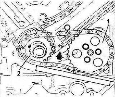
9. Unscrew bolts of fastening of a damper of a chain of a drive of the oil pump and remove it.
10. Remove sprocket 2 from the crankshaft, as well as the oil pump drive chain (see illustration 3.8).
11. Turn the engine until the reference mark on the camshaft sprocket aligns with the mark on the balancing shaft sprocket.
12. Loosen the tension of the balance shaft drive chain by compressing the tensioner spring with a suitable tool, such as 0164-F, which is used in specialized workshops (see illustration)
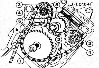
3.12 Relieve tension on the balance shaft drive chain by compressing the tensioner spring with a suitable tool
3 - retaining rings that hold the guide sprockets
4 - guide sprockets of the balancer shaft drive
13. Unscrew bolts 1 and 2 and remove sprockets 5 and 6 together with the balancing shaft drive chain (see illustration 3.12).
14. Measure the protrusions Y of the tensioner plungers of both timing chains (see illustration). If the protrusion of the plungers has reached 9.5 mm or more, then the chains and their sprockets must be replaced.
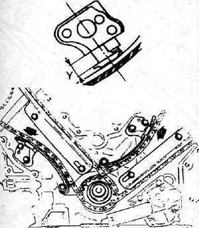
3.14 Measure the protrusions Y of the tensioner plungers of both timing chains
15. Loosen both timing chains by pushing the tensioner plungers deep into the housing and locking them with a pawl using a screwdriver.
16. Unscrew bolts of fastening and remove tensioners of both chains.
Attention! Under the tensioners are the so-called oil filters, through which oil enters the tensioners to lubricate them.
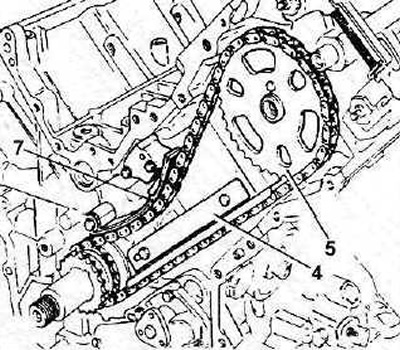
17. Unscrew the fastening bolts and remove the dampers 3 and 4 of the chains, as well as the shoes 6 and 7 of the tensioners (see illustrations 3.18 and 3.19).
18. Unscrew the bolt 1 fastening the sprocket 2 to the camshaft of the rear cylinder head and remove it together with the chain (see illustration).
3.18 Unscrew the bolt 1 fastening the sprocket 2 to the camshaft of the rear cylinder head and remove it together with the chain
19. Remove sprocket 5 from the camshaft of the front cylinder head together with the chain (see illustration).
3.19 Remove sprocket 5 from the camshaft of the front cylinder head together with the chain
20. Remove the drive sprocket from the crankshaft, held on the shaft with a key.