



Table of contents: Inspection 🠇 Replacement 🠇
Inspection
1. For ease of access, fully apply the parking brake, raise the front of the vehicle and support it securely (see "Lifting and installing the car on supports").
2. Check the rubber of the supports for cracks, hardening or separation from the metal. If there are obvious defects, replace the support.
3. Check the tightness of the nuts/bolts securing the supports. If possible, use a torque wrench to check.
4. Check the bearings for wear. To do this, carefully pry up the support with a large screwdriver or other lever and check for play. When this check is not possible, have an assistant move the engine/gearbox back and forth or left and right while observing the mounts. Although some play is inherent even in new elements, you will clearly see increased wear. If excessive play is detected, first check that the bolts/nuts are tightened correctly and then replace the worn parts as described below.
Replacement
Right support (1.9 L engines)
5. Disconnect the ground cable from the battery (see "Disconnecting the battery").
6. Release the latches on the right side and on the top plane of the engine cover, and then remove the cover, being careful not to let the corresponding rubber supports fall out (Figure 4.1, a-c).
7. Place the jack under the engine, placing a wooden block on the jack head. Raise the jack enough to relieve the engine mounts.
8. Remove the three bolts securing the upper bracket of the right engine/gearbox mount to the lower bracket (on the engine). Loosen the single nut securing the upper bracket to the rubber support (figure 20.8).
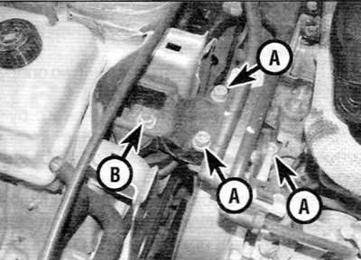
Figure 20.8. Remove the bolts (A), nut (B) and bracket from the top of the right support (1.9 L engines)
9. Remove the upper bracket from the rubber mount and the lower bracket (on the engine), and then remove the rubber buffer plate (if available).
(The source is located on the website: peugeotbook)
10. Using a strap wrench or similar tool, remove the rubber mount from the body. Alternatively, fabricate a tool from a suitable metal pipe, which should have projections that fit into the cutouts in the support.
11. Check all components for signs of wear or damage and replace if necessary.
12. When assembling, screw the rubber support into the body and tighten it securely.
13. Install the rubber buffer plate, then install the upper support bracket and tighten the corresponding bolts and nut to the specified torque.
14. Remove the jack from under the engine. Connect the ground cable to the battery. Install the top cover onto the engine.
Right support (2.0 L engines)
15. Disconnect the ground cable from the battery (see "Disconnecting the battery").
16. Turn the four plastic clips 90° and remove the engine cover (figure 6.25, a, b).
17. Place the jack under the engine, placing a wooden block on the jack head. Raise the jack enough to relieve the engine mounts.
18. On early engines, remove the EGR solenoid valve support bracket mounting bolt and move the valve to the side.
19. Unscrew the two bolts securing the reinforcing bracket of the right support to the body and remove the bracket together with the accelerator pedal position sensor (on later engines) (figure 6.31).
20. Remove the three bolts securing the upper bracket of the right engine/gearbox mount to the lower bracket (on the engine).
21. Loosen the dome-shaped buffer nut, and then loosen the single nut securing the upper bracket to the rubber support (figure 20.21).
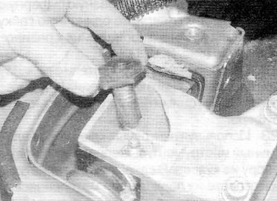
Figure 20.21. Unscrew the domed buffer nut on the top of the support to gain access to the main nut (2.0 L engines)
22. Remove the upper bracket from the rubber support and the lower bracket (on the engine). Then remove the rubber buffer plate.
23. Using a strap wrench or similar tool, remove the rubber mount from the body. Alternatively, fabricate a tool from a suitable metal pipe, which should have projections that fit into the cutouts in the support.
24. Check all components for signs of wear or damage and replace if necessary.
25. When assembling, screw the rubber support into the body and tighten it securely.
26. Install the rubber buffer plate and mount the upper support bracket and tighten the corresponding bolts and nut to the specified torque.
27. Install the reinforcement bracket and secure it with two bolts, which should be tightened to the specified torque. On earlier engines, install the EGR solenoid support bracket onto the reinforcement bracket, install the corresponding bolt and tighten it securely.
28. Remove the jack from under the engine and install the lower protection. Connect the ground cable to the battery. Install the top cover onto the engine.
Left support
29. Contact paragraph 20 of chapter 2B.
Rear support
30. Refer to paragraph Chapter 16 2A.