
Inspection
1. Raise the front of the vehicle and securely jack it up for easier access (see «Lifting and placing the car on supports»).
2. Check the rubber of the supports for cracks, hardening, or separating from the metal. If there are obvious defects, replace the support.
3. Check up reliability of an inhaling of nuts/bolts of fastening of support. If possible, use a torque wrench to check (see 16.3, a, b).
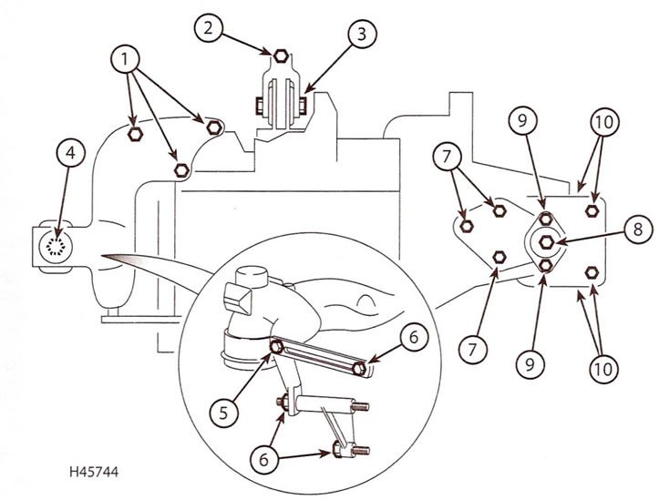
Pic. 16.3, a. Elements and bolts / nuts for fastening the engine / gearbox mounts (late engines 1.4 l)
1. Nuts for fastening the upper bracket of the right support to the bracket on the cylinder block
2. Nut/bolt securing the rear support tie-down to the subframe
3. Nut/bolt securing the rear support tie to the rubber support
4. Nut for fastening the upper bracket of the right support to the rubber support
5. A bolt of fastening of a basic arm of a head of cylinders to the top arm
6. Nut and bolts of fastening of a basic arm of a head of cylinders to the engine
7. Nuts of fastening of an arm of the left support on a transmission
8. Central nut of the left rubber support
9. Nuts / bolts for fastening the left support to the bracket on the body
10. Bolts of fastening of the left support to an arm on a body
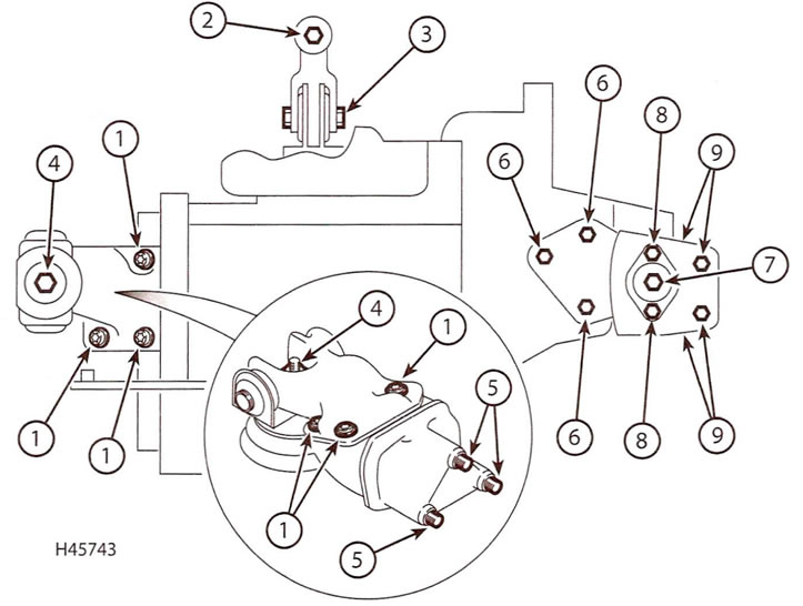
Pic. 16.3, b. Elements and bolts / nuts for fastening the engine / gearbox mounts (engines 1.6 l)
1. Bolts for fastening the upper bracket of the right support to the bracket on the engine
2. Nut/bolt securing the rear support tie-down to the subframe
3. Nut/bolt securing the rear support tie to the rubber support
4. Nut for fastening the upper bracket of the right support to the rubber support
5. Bolts of fastening of the right basic arm of the engine
6. Nuts of fastening of an arm of the left support on a transmission
7. Central nut of the left rubber support
8. Nuts / bolts for fastening the left support to the bracket on the body
9. Bolts for fastening the left support to the bracket on the body
4. Check for wear on the bearings. To do this, carefully pry the support with a large screwdriver or other lever and check for play. When this check is not possible, have an assistant move the engine/gearbox «back forward» or «left-right», and at this time, watch the supports. Although some play is inherent even with new elements, you will clearly see increased wear. If excessive play is found, first check that the bolts/nuts are properly tightened and then replace the worn parts as described below.
Replacement
Right support (engines 1.4 l)
Note. The design of the right mount is slightly different on early and later models, however the removal and installation procedures are the same for both types.
5. Place a jack under the engine by placing a piece of wood on top of the jack head. Raise the jack just enough to relieve the engine mounts.
6. Release the wiring harness and/or vacuum hoses from the clips on the right engine mount upper bracket.
7. Turn away three nuts of fastening of the top arm to an arm on the block of cylinders.
8. On later models, remove the cylinder head support bracket to the front of the upper support bracket.
9. Remove either the single nut or the dome buffer and spacer nut that secures the top bracket to the rubber mount and remove the bracket.
10. Using a strap wrench or similar tool, unscrew the rubber mount from the body. Alternatively, make a tool out of a suitable metal tube, on which the projections should be provided that fit into the cutouts in the support.
11. Check all elements for signs of wear or damage and replace if necessary.
12. When assembling, screw the rubber support into the body and tighten it securely.
13. Install the upper bracket on the rubber support and the bracket on the cylinder block and tighten the appropriate nuts to the prescribed torque. On later models, install the cylinder head support bracket bolt to the top support bracket.
14. Remove the jack from under the engine.
Right support (engines 1.6 l)
15. Place a jack under the engine by placing a piece of wood on top of the jack head. Raise the jack just enough to relieve the engine mounts.
16. Turn out two bolts and move the gauge of position of a pedal of an accelerator and a basic arm aside from the right support of the engine.
17. Release the purge valve vapor hose from the clip on the right leg and move the hose slightly to the side.
18. Turn out three bolts of fastening of the top arm of the right support of the engine to an arm on the engine and turn away the central nut of fastening of an arm to a rubber support on a body. Remove the top support bracket.
19. Using a strap wrench or similar tool, unscrew the rubber mount from the body. Alternatively, make a tool out of a suitable metal tube, on which the projections should be provided that fit into the cutouts in the support.
20. If necessary, remove the three bolts and remove the engine support bracket from the cylinder head.
21. Check all elements for signs of wear or damage and replace if necessary.
22. When assembling, screw the rubber support into the body and tighten it securely.
23. Install the engine support bracket to the cylinder head (if it was taken) and secure it with three bolts, which should be tightened to the specified torque.
24. Install the top bracket onto the rubber mount and motor support bracket and tighten the three bolts and center nut to the specified torque.
25 Install the accelerator pedal position sensor and attach the fuel vapor hose.
26. Remove the jack from under the engine.
Left support
27. Remove the battery and battery tray as described in chapter 5A.
28. Place a jack under the gearbox by placing a piece of wood on top of the jack head. Raise the jack just enough to relieve the transmission mounts.
29. Unscrew the central nut of the rubber support and unscrew the two nuts (or remove two screws) fastening the support to the support bracket. Remove the support from the bracket stud on the gearbox and remove it from the engine compartment. Remove the spacer from the bracket stud on the transmission.
30. If necessary turn out bolts and remove a basic arm from a body. Disconnect the clutch cable from the gearbox (see chapter 6), then remove the nuts and remove the bracket from the top of the gearbox.
31. Carefully check all elements for signs of wear or damage and replace if necessary.
32. Install the bracket on the gearbox, tighten the appropriate nuts to the prescribed torque, then connect the clutch cable (see chapter 6). Install the support bracket to the body and tighten the bolts to the specified torque.
33. Install the spacer on the gearbox bracket, and then slide the rubber support onto the bracket stud on the gearbox. Screw in two nuts/screw in two bolts, screw on the central support nut and tighten it to the prescribed torque.
34. Remove the jack from under the gearbox. Then install the battery tray and battery as described in chapter 5A.
Rear support
35. Install rear wheel chocks if you haven't already. Raise the front of the vehicle and securely jack stands under it (see «Lifting and placing the car on supports»).
36. Turn away a nut and take a bolt of fastening of coupler of a back support to a rubber support on a back part of the block of cylinders.
37. Turn away a nut and take a bolt of fastening of a coupler to a stretcher and remove coupler.
38. To remove the support assembly, you must first remove the right axle shaft, as described in chapter 8.
39. After removal of a semiaxis turn out all bolts and remove a support from a back part of the block of cylinders.
40. Carefully check all elements for signs of wear or damage and replace if necessary.
41. When assembling, install the rear support assembly on the rear of the cylinder block and tighten the appropriate bolts to the prescribed torque. Install the axle shaft as described in chapter 8.
42. Install the rear support tie and tighten both nuts/both bolts to the specified torque.
43. Lower the car.