
Note. Wait for the engine to cool before removing the cylinder head.
Removing
1. Disconnect the ground wire from the battery (see «Disconnecting the battery»).
2. Drain the coolant from the cooling system as described in chapter 1A.
3. Remove the ignition coil pack (see chapter 5B), and then remove the spark plugs (see chapter 1A).
4. Remove the cover (-And) cylinder heads as described in paragraph 4.
5. Remove the upper and lower timing belt covers as described in paragraph 5.
6. Align the mounting holes for the engine/camshaft assembly as described in paragraph 3, and lock the toothed pulley (-s) camshaft and flywheel.
Warning. Do not attempt to crank the engine with the locking tools installed.
Engines 1.4 l
7. The following description is based on the assumption that the cylinder head will be removed along with the intake and exhaust manifolds. This is simpler, but requires handling a bulkier and heavier assembly. If you want to remove the manifolds first, proceed as described in chapter 4A.
8. Perform the following steps as described in chapter 4A:
- A) Remove the air filter assembly and air intake duct.
- b) Disconnect the exhaust pipe from the manifold and from the bracket on the gearbox. Disconnect or release the oxygen sensor harness.
- V) Disconnect the supply fuel hose (and, if applicable, return hose) from the fuel rail (plug all openings to prevent fuel from escaping and dirt from entering the fuel system).
- G) Mark the installation position of the electrical connectors and vacuum/vent hoses on the intake manifold and throttle body, and then disconnect and disconnect them.
- d) If necessary, remove the bolts and remove the support bracket from the intake manifold.
- e) Disconnect the accelerator cable (in the presence of).
- and) On models with air injection, disconnect the hose from the fuel injection valve located on the exhaust manifold.
9. Release collars and disconnect hoses of a cooling liquid from a head of cylinders, having previously noted position of their installation. Similarly, mark the location, and then disconnect all electrical connectors on the cylinder head.
10. Release and turn out a bolt of fastening of a tube of a dipstick of measurement of level of engine oil to a head of cylinders.
11. On later models with power steering, remove the power steering pump mounting bolt on the appropriate support bracket (see chapter 10). Remove the screws securing the power steering pipe clamp, and then position the pump away from the engine. Tie the pump properly to the vehicle body to prevent excessive deformation of the lines/hoses. Note. There is no need to disconnect the piping/hose from the pump.
12. Loosen the timing belt tensioner pulley nut. Rotate the pulley approximately 60°clockwise with a wrench inserted into the hole in the pulley hub, and then re-tighten the appropriate nut. Early engines will require an 8mm square wrench, and later auto-tensioner engines will require an internal hex wrench.
13. Remove the timing belt from the camshaft sprocket and position the belt away from the camshaft sprocket. Do not sharply bend or twist the belt.
14. Working in sequence, reverse tightening sequence (pic. 11.39 a.m), gradually loosen the cylinder head bolts, doing half a turn at a time, so that all the bolts can be unscrewed by hand (pic. 11.14).
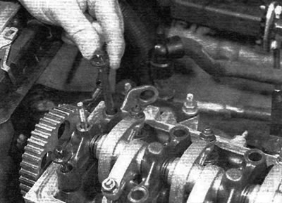
Pic. 11.14. Release and turn out bolts of fastening of a head of cylinders (engines 1.4 l)
15. After unscrewing all the cylinder head bolts, remove the valve lever assembly from the cylinder head (pic. 11.15). Note. Do not touch the running surfaces of the valve lever roller bearings with your fingers. Note the dowel pins that are located on the base of each valve arm assembly support. If any pin is loose in the head or bearing, remove it and store it in a safe place.
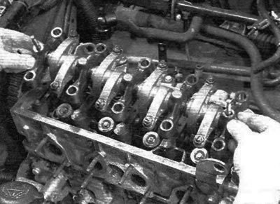
Pic. 11.15. Remove the valve lever assembly (engines 1.4 l)
16. Now you should open the joint between the cylinder head with the gasket and the cylinder block / crankcase without disturbing «wet» sleeves. To open the joint, take two strong screwdrivers and insert them into the holes for the cylinder head bolts. To release the cylinder head, carefully «rock» towards the front of the car (pic. 11.16). Do not attempt to turn the head in a horizontal plane relative to the cylinder block/crankcase, as its position is set by the dowel pins as well as the top sections of the liners.
Note. If you are not careful and the sleeves are misaligned, it is possible that the seals at the base of the sleeves will fail, causing leakage after the head is installed. After opening the joint, lift the cylinder head and remove it. Get a helper if possible, as this is a bulky assembly, especially if the head is removed with the manifolds.
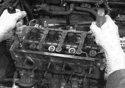
Pic. 11.16. Use two strong screwdrivers to separate the cylinder head from the cylinder block (engines 1.4 l)
17. Remove the gasket from the top plane of the block; note the two dowel pins. If the dowel pins are loose, remove them and store in a safe place along with the head. Do not throw away the gasket; required for identification purposes (see paragraphs 29 and 30). Actions that require turning the crankshaft (e.g. cleaning piston crowns), should be carried out only after ensuring that the cylinder liners are securely fixed (pic. 11.17). In the absence of special sleeve clamps from the manufacturer, the sleeves can be fixed using large flat washers mounted under bolts of suitable length. Alternatively, the original cylinder head bolts can be temporarily installed by fitting suitable spacers.
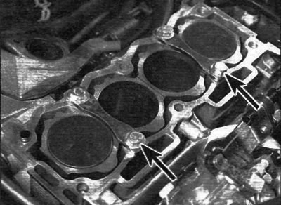
Pic. 11.17. Clamp the cylinder liners before turning the crankshaft (clamps are marked with arrows) (engines 1.4 l)
18. If the cylinder head must be disassembled for overhaul, remove the camshaft as described in paragraph 10, and then refer to chapter 2D.
Engines 1.6 l
19. Mark the installation position, then release the clamps and disconnect the coolant hoses from the cylinder head. Mark the location and then disconnect all electrical connectors on the cylinder head.
20. Remove the intake and exhaust manifolds as described in chapter 4A.
21. Remove the inner timing belt cover as described in paragraph 5.
22. Working in sequence, reverse tightening sequence (pic. 11.39, b), gradually loosen the cylinder head bolts, half a turn at a time, until all bolts can be removed by hand.
23. Raise the cylinder head and remove it. Get a helper if possible, as this is a bulky knot.
24. Remove the gasket from the top plane of the block; note the two dowel pins. If the dowel pins are loose, remove them and store in a safe place along with the head. Do not throw away the gasket; required for identification purposes (see paragraphs 29 and 30).
25. If the cylinder head must be disassembled for overhaul, remove the camshafts as described in paragraph 10, and refer to part D of this chapter.
Preparing for installation
26. Before installing the cylinder head, thoroughly clean the mating surfaces of the cylinder head and cylinder block/crankcase. Use a hard plastic or wooden scraper to remove gasket residue and carbon deposits. Clean the piston bottoms.
Note. On 1.4 liter engines, tighten the sleeves before turning the crankshaft (see item 17). Be extremely careful when cleaning, the soft aluminum alloy is easily damaged. Do not allow carbon deposits to enter the lubrication and coolant channels. This is especially important for the lubrication system, since carbon deposits can block the oil supply to the engine elements. Cover the cooling and lubrication channels and bolt holes in the cylinder block/crankcase with adhesive tape and paper. In order to prevent the removed deposits from getting into the gaps between the pistons and the cylinder walls, put a little grease into the gap. After cleaning each piston, take a small brush and remove all traces of grease and carbon from the gap, then wipe everything with a clean cloth. Also clean all pistons.
27. Check the mating surfaces of the cylinder block/crankcase and cylinder head for nicks, deep scratches and other damage. If they are small, carefully remove them with a file. But if they are large, the only alternative to replacement may be only mechanical processing.
28. If deformation of the mating surface of the cylinder head is suspected (under the gasket), check this surface with a ruler. If necessary, contact chapter 2D.
29. When buying a new cylinder head gasket, care should be taken to ensure that the gasket has the correct thickness. Some models only use one thickness of spacer, in which case this is not a problem. Other models have pads in two different thicknesses: a standard pad and a slightly thicker pad (+0.2 mm) «repair» pad. Gaskets can be recognized, as described in the next paragraph, by cutouts on the left edge of the gasket.
30. With the correct location of the gasket on the upper plane of the cylinder block, one or two cutouts will be visible on the left side of the gasket closer to the rear edge, which show the type of engine (e.g. TU3JP engine). There may be another group of cutouts in the center of the gasket (0 to 4), showing the manufacturer of the gasket and the presence of asbestos in its material (these cutouts are of little value). An important group of cutouts is located on the front side of the gasket; on a standard gasket there will be no notch in this place, but on a thicker «repair» the gasket will have one notch (pic. 11.30). Determine the gasket type and ensure that the new gasket is the correct thickness. If there is any doubt as to which gasket is installed, show «old» gasket to your dealer and ask them to confirm the type of gasket.
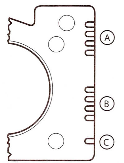
Pic. 11.30. Identification cutouts on the cylinder head gasket
A Group of engine type identification cutouts
B Gasket manufacturer identification cutout group
C Group of identification cutouts for gasket thickness
31. Check up a condition of bolts of fastening of a head of cylinders, especially a carving. This should be done every time the bolts are removed. Wash the bolts in an appropriate solvent and wipe dry. Check each bolt for signs of wear or damage, replace if necessary. Measure the length of each bolt from the back of its head to the end of the bolt to check for stretch (pic. 11.31). New bolts for 1.4L engines are 175.5mm long; if the bolt is stretched to more than 176.5 mm, replace all cylinder head bolts with a single set. On 1.6L engines, the maximum bolt length is 122.6mm. Although the manufacturer does not actually prescribe the need to replace the bolts, it is strongly recommended to replace the bolts as a single set, regardless of their external condition, each time they are unscrewed.
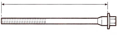
Pic. 11.31. Measure the length of the bolt from the back of the head to the end of the bolt
32. On 1.4 liter engines, before installing the cylinder head, check the protrusion of the cylinder liners, as described in paragraph 11 of chapter 2D.
Installation
Engines 1.4 l
33. Wipe clean the mating surfaces of the cylinder block/crankcase and cylinder head. Ensure that the two dowel pins are in place on each edge of the cylinder block/crankcase mating surface and remove the cylinder liner retaining clips if necessary (pic. 11.33).
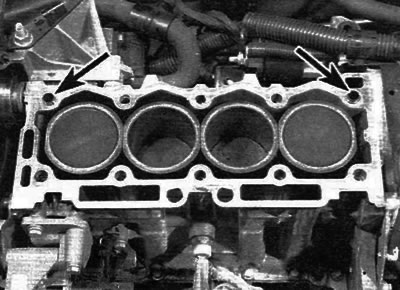
Pic. 11.33. Make sure dowel pins are present (marked with arrows) and install a new cylinder head gasket
34. Install a new gasket on the cylinder block/crankcase mating surface, orienting it so that the identification cutouts are located on the left edge of the gasket, and the side with the marking «TOR» was turned upward.
35. Make sure that the flywheel and camshaft sprocket are still properly locked using the appropriate tools, and then, with the help of two people, carefully install the cylinder head on the block, exposing it over the locating pins.
36. Ensure that the dowel pins are in place at the base of each valve arm support, and then install the valve arm assembly to the cylinder head.
37. Lightly lubricate the threads and reverse side of the heads of the cylinder head bolts with clean engine oil.
38. Carefully insert each bolt into the appropriate hole (don't let them fall) and screw them in by hand only.
39. Working gradually and in the prescribed sequence, using a torque wrench and a suitable end head, tighten the cylinder head bolts to the prescribed torque according to stage 1 (pic. 11.39, a, b).
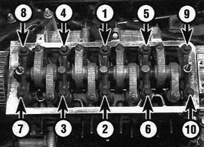
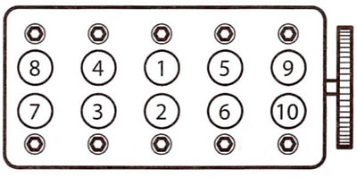
Pic. 11.39 a.m. Tightening sequence - cylinder head bolts (engines 1.4 l)
Pic. 11.39 b. Cylinder head bolt tightening sequence (engines 1.6 l)
40. Once all the bolts have been tightened according to stage 1, working again in the same sequence, use a socket and extension to tighten the bolts to the specified angle according to stage 2. To ensure accuracy at this stage of tightening, it is recommended to use a goniometer. If a goniometer is not available, mark the relative position with white paint on the bolt head and cylinder head before tightening. The marks can then be used to check that the bolts have been turned to the correct angle when tightened.
41. Install the timing belt as described in paragraph 6.
42. Connect all coolant hoses to cylinder head, intake manifold and throttle body. Connect all relevant electrical connectors.
43. Screw in the bolt that secures the dipstick tube to measure the engine oil level to the cylinder head.
44. Working as described in chapter 4A, do the following:
- A) Connect all disturbed fuel hoses and cable (-s) controls to the intake manifold and fuel system elements.
- b) Connect and adjust the accelerator cable (in the presence of).
- V) Connect the exhaust system downpipe to the transmission manifold and bracket, and dock the oxygen sensor electrical connector.
- G) Install the air filter assembly and intake ducts.
45. Check and, if necessary, adjust the valve clearances as described in paragraph 9.
46. Install the cylinder head cover as described in paragraph 4.
47. Install the spark plugs and install the ignition coil (see chapter 1A and 5 B).
48. Install the power steering pump as described in chapter 10.
49. Finally, connect the battery and recharge the cooling system as described in chapter 1A.
Engines 1.6 l
50. Remove the flywheel locking tool and use a wrench or socket to rotate the crankshaft by the crankshaft pulley bolt in the opposite direction (counterclock-wise) 90°. This is to prevent any accidental contact between the pistons and valves when installing the cylinder head.
51. Be convinced that camshafts are correctly located in a head of cylinders. The alignment groove on the right side of each camshaft must be in position «7 o'clock» on the intake camshaft and in position «8 ocloc'k» on the exhaust camshaft (pic. 10.32). If necessary, adjust the position of the camshafts by turning each shaft with an open end wrench on the rectangular section between the cams.
52. Wipe clean the mating surfaces of the cylinder block/crankcase and cylinder head. Ensure that there are two dowel pins on each edge of the engine block/crankcase mating surface.
53. Install a new gasket on the cylinder block/crankcase mating surface, orienting it so that the identification cutouts are located on the left edge of the gasket, and the side with the marking «TOR» was turned upward.
54. Lightly lubricate the threads and the reverse side of the heads of the cylinder head bolts with clean engine oil, and then screw in and tighten the bolts as described in paragraphs 38-40.
55. Install the timing belt inner cover as described in paragraph 5, and then install the camshaft sprocket as described in paragraph 7.
56. Install the timing belt as described in paragraph 6.
57. Working as described in chapter 4A, do the following:
- A) Install the intake and exhaust manifolds.
- b) Connect all disturbed fuel hoses and cable (-s) controls to the intake manifold and fuel system elements.
- V) Install the air filter assembly and intake ducts.
58. Connect all coolant hoses to the cylinder head, intake manifold and throttle body. Connect all relevant electrical connectors.
59. Install the cylinder head covers as described in paragraph 4.
60. Install the spark plugs and install the ignition coil (see chapter 1A and 5 B).
61. Finally, connect the battery and charge the cooling system as described in chapter 1A.