
Note. Valve clearances should only be checked and adjusted when the engine is cold.
Note. This procedure only applies to 1.4L engines. Valve clearances on 1.6 liter engines are maintained by hydraulic compensators built into the valve lifters.
1. The importance of proper valve clearance adjustment cannot be overestimated, as they have a significant impact on the dynamic performance of the engine. If the clearances are too large, the motor will make noise when running (knocking or rattling), and engine efficiency will be reduced as the valves open too late and close too early. A more serious problem occurs if the gaps are too small. In this case, the valves cannot close fully when the engine is hot, resulting in severe engine damage (e.g. burnt valve seats and/or deformation/cracking of the cylinder head). Checking and adjusting clearances is done as described below.
2. Remove the cylinder head cover as described in paragraph 4.
3. The engine can now be turned using a suitable socket and extension for the crankshaft sprocket bolt.
4. The clearance in each valve should only be checked and adjusted with the valve fully closed, with the valve lever resting on «heel» cam (just the opposite «sock»). This can be achieved by making adjustments in the following sequence. Keep in mind that cylinder #1 is closest to the gearbox. The correct valve clearances are given in «Specifications» at the beginning of this chapter. The location of the valves can be determined by the position of the manifolds.
Fully open valve
- Graduation №1
- Graduation №3
- Graduation №4
- Graduation №2
Adjustable valves
- Inlet No. 3 and Outlet No. 4
- Inlet No. 4 and Outlet No. 2
- Inlet No. 2 and Outlet No. 1
- Inlet No. 1 and Outlet No. 3
5. With the corresponding valve fully open, check the clearances in the two prescribed valves. To check the clearance, insert a feeler gauge of the correct thickness between the valve stem and the valve lever adjusting screw. The probe should pass in a slight sliding fit. If adjustment is necessary, loosen the locknut on the adjusting screw and turn the screw if necessary (pic. 9.5).
When the correct clearance is reached, hold the adjusting screw and tighten the locknut securely. After tightening the locknut, check the valve clearance again and re-adjust if necessary.
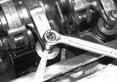
Pic. 9.5. Check valve clearances with «fan» probe
6. Rotate the crankshaft until the next valve in the prescribed sequence is fully open and check the clearances in the next two prescribed valves.
7. Repeat the procedure until you complete the check (and, if necessary, adjustment) gaps in all eight valves, and then install the cylinder head cover as described in paragraph 4.