



Fixing the camshaft
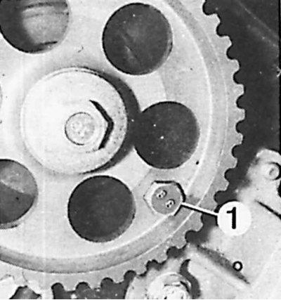
1 – locking bolt
Valve clearance should only be adjusted in cases where increased fuel consumption, incorrect adjustment, replacement or adjustment of valves, replacement of tappets or camshaft are detected.
Examination
The valve clearance is checked when the engine is cold.
1. On naturally aspirated engines, remove the air duct.
2. On turbocharged engines, remove the boost cooler.
3. Remove the head cover.
4. Remove the glow plugs.
5. Remove the right pulley and housing.
6. Check the valve clearances in two steps:
- bring the valve of cylinder No.4 to the state of opening. Check the valve clearances of cylinders No.: 1 - inlet, 1 - outlet, 2 - inlet, 3 - outlet;
- bring the valve of cylinder No.1 to the state of opening. Check the valve clearances of cylinders No.: 4 - inlet, 4 - outlet, 3 - inlet, 2 - outlet.
Valve clearances (the engine is cold)
| Inlet valve | 0.15 mm |
| Exhaust valve | 0.30 mm |
| Admission | ±0.08 mm |
Adjustment
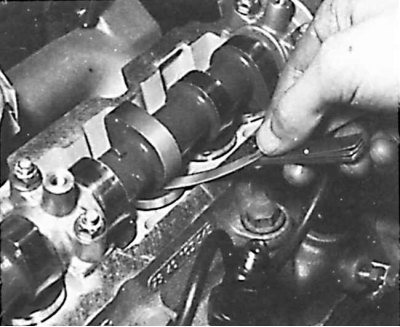
1. Check the valve clearances according to the method described above and record the measured values.
2. Loosen the camshaft drive belt and remove it from the camshaft pulley.
3. Lock the camshaft pulley with a special bolt and unscrew the mounting bolt.
4. Remove the pulley.
5. Remove the camshaft bearing caps and camshaft.
6. Remove the tappets and install them in order.
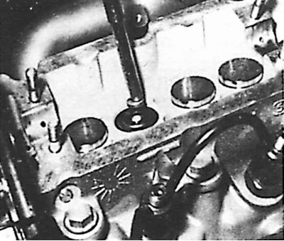
7. Remove the adjusting plates and measure their thickness.
8. Determine the required thickness of the adjustment plates:
- if the measured gap is too small, a thinner plate should be installed (see table. Example A);
- if the measured gap is too large, a thicker plate should be installed (see table. Example B).
Attention! After replacing one of the valve timing system parts or after grinding the valves, 8 adjusting plates with a thickness of at least 2.425 mm must be installed.
9. Install the tappets with adjusting plates of the required thickness.
Data published on the website: PEUGEOTBOOK
10. Install new O-rings.
11. Install the camshaft pulley.
12. Check the camshaft installation.
13. Install and adjust the timing belt tension.
14. Install the timing case cover.
15. Install the seal, secure the cylinder head cover and other removed parts.
Examples of valve clearance adjustment
Example A
| Required clearance | 0.15 mm (inlet) |
| Measured gap | 0.25 mm |
| Difference | 0.10 mm |
| Thickness of the installed plate | 2.35 mm |
| The thickness of the plate to be installed | 2.45 mm |
| The resulting gap | 0.15 mm |
Example B
| Required clearance | 0.30 mm (release) |
| Measured gap | 0.25 mm |
| Difference | -0.05 mm |
| Thickness of the installed plate | 2.925 mm |
| The thickness of the plate to be installed | 2.875 mm |
| The resulting gap | 0.30 mm |