



Table of contents: 1.9L engines 🠇 2.0L engines 🠇
1.9L engines
Examination
1. The importance of correct valve clearance adjustment cannot be overestimated, as they have a significant impact on the dynamic characteristics of the engine. However, the inspection should not be regarded as a planned operation. It should be performed when the valve train is noisy, after a major engine overhaul, or when trying to find the cause of power loss. Checking the clearances is performed as described below. To ensure accuracy of the check, it should be performed on a cold engine.
2. Fully apply the parking brake. Raise the front of the vehicle and support it securely (see "Lifting and installing the car on supports"). To gain access to the right end of the engine, you need to remove the plastic wheel arch liner. The mudguard is secured to the wheel arch with various screws and fasteners. Release all fasteners and remove the mudguard from under the front fender. If necessary, release the coolant hoses from under the fender to facilitate further access.
3. The engine can now be turned using a suitable socket head and extension on the crankshaft pulley bolt. Please note that the crankshaft should only be turned clockwise (when looking from the right side of the car).
4. Remove the cylinder head cover as described in paragraph 4.
5. Take a piece of paper and draw an outline of the engine in plan, indicating the cylinders, which are numbered starting from the flywheel. Show the position of each valve and record the prescribed valve clearance value. Draw lines above each valve position to record the actual clearance (1) and the required adjustment value (2) (figure 12.5).
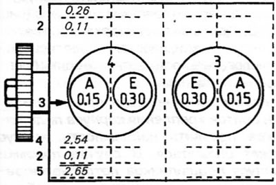
Figure 12.5. Example of calculating the thickness of the adjusting shim (1.9 L engines)
A. Inlet valve
E. Exhaust valve
1. Measured gap
2. Difference compared to the prescribed value (3)
3. Prescribed clearance
4. Thickness of the installed adjusting shim
5. Thickness of the required adjusting shim
6. Turn the crankshaft so that the inlet valve of cylinder No. 1 (closest to the gearbox) was completely closed, that is, the tip of the cam was facing away from the pusher.
7. Using a fan gauge, measure the clearance between the base of the cam and the tappet (figure 12.7). Record the gap value on line (1).
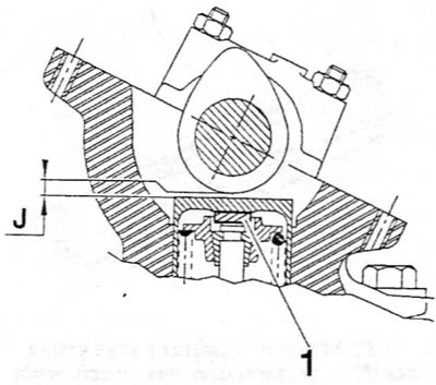
Figure 12.7. Measuring the valve clearance (J). The clearance is adjusted by replacing the adjusting shim (1) (1.9 L engines)
8. Repeat the measurements for the remaining seven valves, rotating the crankshaft if necessary so that the corresponding cam always faces away from its mating tappet.
9. Calculate the difference between each measured clearance and the required value and record the result on line (2). Since clearances for intake and exhaust valves are different, make sure you know which valve you are dealing with. The valve arrangement sequence when counting from either end of the engine:
Intake — Exhaust — Exhaust — Intake — Intake — Exhaust — Exhaust — Intake.
10. If all clearances are within specifications, install the cylinder head cover (see paragraph 4). Install the wheel arch liner. Lower the car. If any measured clearance is not within specification, adjustment should be made as described in the following paragraphs.
Adjustment
11. Remove the camshaft as described in paragraph 11.
12. Remove the first pusher together with its adjusting shim. Clean the adjusting shim and measure its thickness with a micrometer. The shims are marked with thickness, but wear can cause the original thickness to decrease. Therefore, please check the specified value.
13. Refer to the clearance values recorded for the valve in question. If the clearance was greater than specified, the thickness of the adjusting shim should be increased by the difference recorded on line (2). If the clearance was less than specified, the thickness of the adjusting shim should be decreased by the difference recorded on line (2).
14. Draw three more lines under each valve position on the check sheet as shown in the figure (figure 12.5). On line (4), record the measured shim thickness, and then add or subtract the difference indicated on line (2) to obtain the final value for the required shim thickness, which should be recorded on line (5).
15. Repeat the procedure according to paragraph. p. 12-14 on the remaining valves, maintaining the order of the arrangement of all tappets.
[Article based on material from the website PeugeotBook.ru]
16. Prepare the adjusting shims required to bring each valve clearance to specification. Keep in mind that the shims can be swapped, but the tappets cannot.
17. When assembling, lubricate the adjusting shim and install it on the valve plate with the size marking facing down. Lubricate the push rod and lower it onto the adjusting shim. Do not lift the pushrod after installation as the adjusting shim may become displaced.
18. When all the tappets together with their adjusting shims are in their standard place, install the camshaft as described in paragraph 11. Before installing the cylinder head cover, check the valve clearances again to ensure they are correct.
2.0L engines
19. The 2.0L engine is equipped with hydraulic tappets that automatically adjust valve clearances. Therefore, there is no need to check or adjust valve clearances.