



2. Gently pry the rings apart to release them from the grooves. To prevent the rings from springing back into the vacated grooves, use two or three old feeler gauges (figure 13.2). Be careful not to scratch the piston with the ends of the ring lock. The rings are fragile and will break if you push them too hard. They are also very sharp, so protect your palms and fingers. Keep in mind that in the third (oil scraper) the ring has a built-in spacer element (expander). Always remove rings through the top of the piston. If you are installing "old" rings, store each set of rings with the corresponding piston.
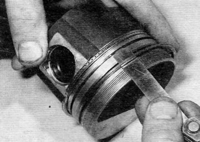
Figure 13.2. Removing a piston ring using a flat feeler gauge
3. Use a scraper to remove carbon deposits from the top of the piston. Once most of the deposits have been removed, a wire brush can be used (or fine-grained sandpaper).
4. Remove carbon deposits from the piston grooves. To do this, use an "old" ring. Break the ring in half (be careful not to cut your fingers—piston rings are very sharp).
Warning. Be careful to remove only the carbon deposits - do not remove metal or scratch the sides of the grooves.
5. After removing the carbon deposits, clean the piston and connecting rod assembly with kerosene or a suitable solvent and dry thoroughly. Clean the oil return holes (in the grooves).
6. If the pistons and cylinder mirrors are not damaged and do not have increased wear, and the cylinder block does not require cylinder boring, the original pistons can be installed in place. Normal piston wear appears as uniform vertical wear on the piston surfaces subject to lateral pressure and slight looseness of the top ring in the corresponding groove. When assembling the engine, be sure to use new piston rings.
7. Carefully inspect each piston for cracks in the skirt, around the piston pin bore, and in the areas between the piston ring grooves.
8. Inspect the piston for holes in the piston head, a "burned" area on the edge of the head, and scratches and wear on the skirt. If the skirt is scratched or worn, the engine may have been overheated and/or experienced abnormal combustion resulting in excessively high operating temperatures. The cooling and lubrication systems should be carefully checked. Burn marks on the piston walls indicate a gas breakthrough. A hole in the piston crown or "burned" areas on the edge of the piston crown indicate abnormal combustion (premature ignition or detonation). If any of these defects are present, their causes should be identified and corrected. Otherwise, the damage will occur again. The reasons may be incorrect injection advance or faulty injectors (whichever is applicable).
9. Piston pitting indicates coolant leakage into the combustion chamber and/or crankcase. The cause must be eliminated. If this is not done, the problem may also appear on a rebuilt engine.
10. Carefully inspect each connecting rod for signs of damage such as cracks near the big-end and big-end bearings. Check if the connecting rod is bent. Unless the engine was seized or severely overheated, damage is very unlikely. A detailed inspection of the connecting rod assembly can only be performed by a dealer or engine repair specialist with the necessary equipment.
11. The connecting rod bearing cap nuts should be replaced after each unscrewing. Although Peugeot/Citroen does not specify that the bolts should also be replaced, it is recommended that the nuts and bolts be replaced as a set.
12. Piston pins - floating type. Fixation is ensured by retaining rings. The pistons can be separated from the connecting rods by proceeding as described below.
13. Using a small flat-head screwdriver, remove the retaining rings from the piston and push out the piston pin (Figure 13.13, a-c). Hand force should be sufficient to remove the pin. Mark the piston and connecting rod to ensure proper assembly. Discard the retaining rings; new ones should be used during assembly.
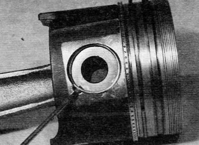
Figure 13.13, a. Remove the retaining ring...
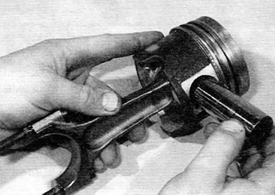
Figure 13.13, b....remove the piston pin
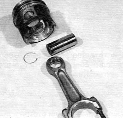
Figure 13.13, c....and separate the piston from the connecting rod
14. Inspect the piston pin and big end bearing for signs of wear or damage. If worn, both the piston pin and the bushing will need to be replaced. The situation can be corrected by replacing both the pin and the bushing. However, replacing the bushing is a job for a specialist: a press is required, and the new bushing must be reamed to the required size.
15. The connecting rods themselves should not require replacement unless the engine has seized or some other major mechanical failure has occurred. Visually inspect the connecting rod geometry and if they are warped, have them examined by an engine overhaul specialist. He can perform a more detailed check.
16. Inspect all elements. Obtain the necessary new parts from your dealer or engine repair specialist. If you purchase new pistons, please be aware that they will come complete with piston pins and retaining rings. Retaining rings can also be purchased separately.
17. Assemble the piston and connecting rod so that the cutout or arrow on the piston crown or the valve recess on the piston crown are positioned as shown relative to the cutouts in the connecting rod small-end bearing shells (figure 13.17, a, b). Apply a small amount of clean motor oil to the piston pin. Insert your pin into the piston and pass it through the small end of the connecting rod. Check if the piston rotates freely on the connecting rod. Secure the piston pin with two new snap rings. Make sure that each snap ring is properly seated in its corresponding groove on the piston.
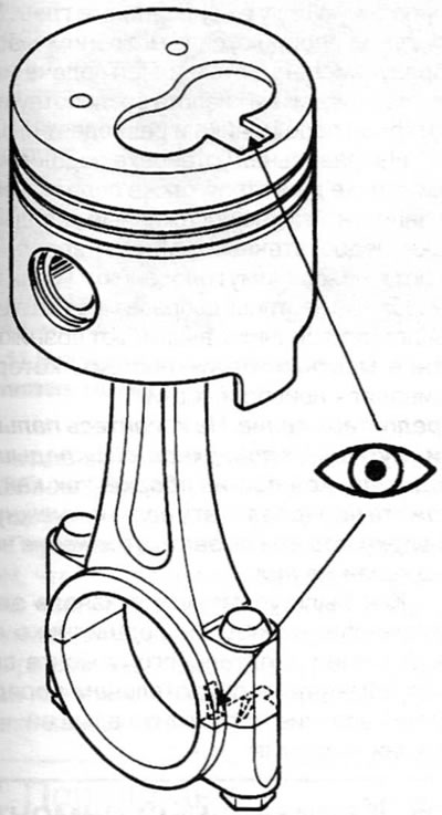
Figure 13.17, a. On 1.8L and 1.9L engines, ensure that the recess in the piston crown is positioned relative to the cutout in the connecting rod bearing shell, as shown
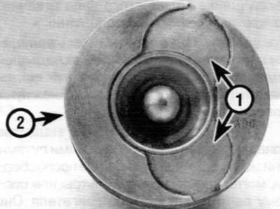
Figure 13.17, b. On 2.0 L engines, the valve recess (1) on the piston crown should be located on the side opposite to the cutout in the connecting rod bearing shell (2, not visible)