
Selection of bearing shells
1. Have the crankshaft inspected and measured by an engine overhauler. Specialists will be able to perform any regrinding / repair and select the appropriate liners for main and connecting rod bearings.
Installation
2. If applicable, install oil jets in the bearing area of the cylinder block.
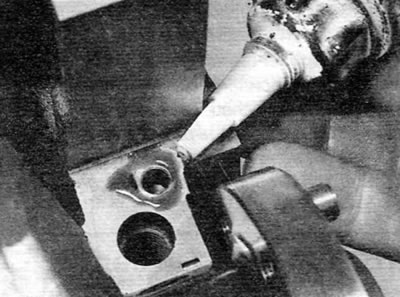
3. Using a little grease, glue the top thrust washers to each side of the top of the #2 main bearing. Make sure the grease grooves on each thrust washer are facing out (away from the cylinder block) (pic. 18.3).
Pic. 18.3. Install the upper thrust washers on the No. 2 main bearing with the oil groove facing out
4. Wipe clean the backs of the bearing shells and the bearing mounting areas in both the cylinder block/crankcase and bearing caps. Install the bushings in their original positions, making sure that the tab on each bushing fits into the groove in the cylinder block/crankcase or bearing cap. Be careful not to touch the running surfaces of the bearing shells with your fingers. Keep in mind that the upper shells of all bearings have a groove, the lower shells have a normal smooth surface (pic. 18.4, a, b). If new bearings are installed, use kerosene to remove all traces of protective grease from them. Dry the bearings and connecting rods with a lint-free cloth. Liberally coat each bearing shell in the cylinder block/crankcase and cap with clean engine oil.
Pic. 18.4, a. Install the bearing shells, making sure that the lugs fit into the grooves in the cylinder block/crankcase...
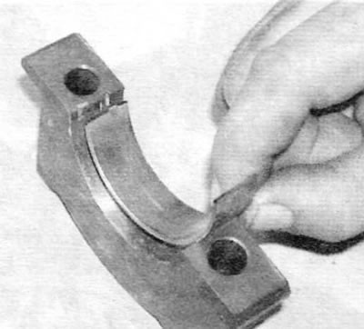
Pic. 18.4, b....and in the bearing cap
5. Install the crankshaft in place so that the connecting rod necks No. 2 and 3 are in the TDC position; the connecting rod journals of cylinders No. 1 and 4 will be in the BDC position. This is the position ready to install piston No. 1. Check the crankshaft end play as described in paragraph 14.
6. Lubricate the lower bearing shells with clean engine oil. Make sure that the mounting protrusions on the inserts fit into the corresponding recesses in the covers.
7. Install main bearing caps #2-5 in original position, orienting correctly (the projections on the bearing shells and the recesses in the block and covers must be located on the same side). Screw in the bolts and at this stage only lightly tighten them.
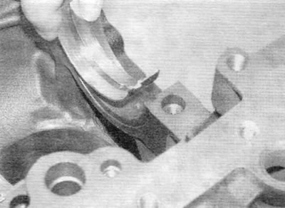
8. Apply a small amount of sealant to the surface of the cylinder block mating with the No. 1 main bearing cap around the seal strip holes (pic. 18.8).
Pic. 18.8. Applying sealant to the surface of the cylinder block mating with the No. 1 main bearing cap
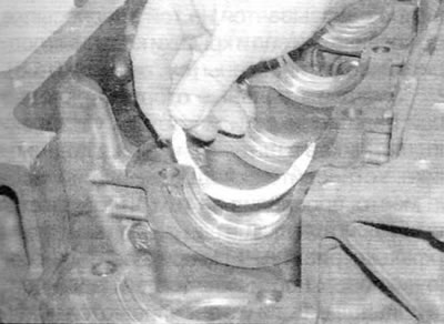
9. Position the lip of each sealing strip on the pins on the base of the No. 1 bearing cap and press the strips into the grooves on the bearing cap. Two thin metal strips of 0.25 mm or less must now be prepared to prevent the strips from moving when the cover is installed. Peugeot/Citroen service stations use the tool shown to act as a clamp. You can use metal strips (For example, «old» probes), provided that they are free of all burrs that could damage the seals (pic. 18.9, a, b).
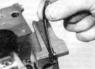
Pic. 18.9, a. Installing the Sealing Strip on the No. 1 Main Bearing Cap
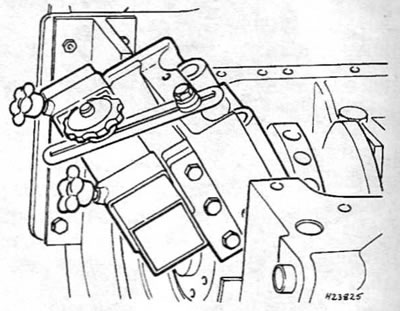
Pic. 18.9, b. Using a Peugeot Special Tool to Install No. 1 Main Bearing Cap
10. Lubricate both sides of the metal strips with oil and hold them against the sealing strips. Install the No. 1 main bearing cap, loosely screw in the bolts, and then use a pair of pliers to carefully pull out the metal strips horizontally (pic. 18.10, a, b).
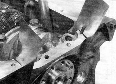
Pic. 18.10, a. Installing the No. 1 main bearing cap, using metal strips to maintain the side seals
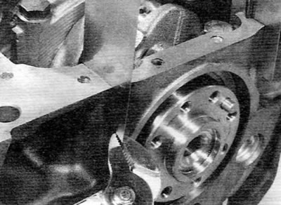
Pic. 18.10, b. Removing the metal strip from the No. 1 main bearing cap with pliers
11. Evenly tighten all the bolts of the main bearing caps to the specified torque, and on 2.0 liter engines, additionally tighten to the specified angle.
12. Make sure that the sealing strips protrude slightly above the mating surface of the cylinder block/crankcase, approximately 1.0 mm. If not, remove the bearing cap again and reinstall it; The seals are in the correct length as delivered and should not be cut. Also make sure that the crankshaft is free to turn.
13. Install a new cuff on the crankshaft, as described in chapter 2B or 2B (whichever is applicable).
14. Install the pistons and connecting rods to the crankshaft as described in paragraph 19.
15. Install the key, and then install the oil pump drive sprocket and spacer (in the presence of) and put the drive chain on the sprocket.
16. Clear and dry interfaced surfaces of the case of a cuff and the block of cylinders. Mark the depth of the cuff installation, and then use a large flat screwdriver to remove «old» cuff from the body.
17. Apply a bead of suitable sealant to the mating surface of the oil seal housing. Make sure the dowel pins are present. Install the cuff housing on the end of the crankshaft and then bring it to its original position on the cylinder block. Tighten the housing bolts securely.
18. Install a new crankshaft seal as described in chapter 2B or 2B.
19. After making sure that the drive chain is correctly put on the sprocket, install the oil pump and oil pan as described in chapter 2B or 2B (whichever is applicable).
20. Install the cylinder head (if it was taken), as described in chapter 2B or 2B or in paragraph 5 of this chapter (whichever is applicable).