
Crankshaft
Right cuff
1. Remove the timing belt crankshaft sprocket as described in paragraph 8.
2. Mark the insertion depth of the cuff.
3. Using the hook tool, pull the cuff out of the body. Alternatively, drill a small hole in the cuff and pull it out using a self-tapping screw and pliers (pic. 16.3).
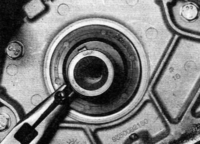
Pic. 16.3. Using a self-tapping screw and pliers to remove the right crankshaft seal
4. Clean the oil seal housing and the sealing surface of the crankshaft.
5. Dip a new seal in clean engine oil and insert it into the body (open edge out) to the depth marked at removal, using a suitable piece of pipe with machined ends or a socket head. A piece of thin plastic or adhesive tape wrapped around the front end of the crankshaft helps prevent damage to the oil seal when it is installed.
6. Remove the plastic or tape from the end of the crankshaft, if applicable.
7. Install the toothed pulley on the crankshaft as described in paragraph 8.
Left cuff
8. Remove the flywheel as described in paragraph 18.
9. Follow the steps described in paragraphs 2-6. Keep in mind that when installing, the outer sealing lip of the collar must face outward; if it's facing in, use a piece of bent wire to pull it out. Be careful not to damage the cuff.
10. Install the flywheel as described in paragraph 18.
Camshaft
Right cuff
11. Remove the camshaft sprocket as described in paragraph 8. In principle, there is no need to completely remove the timing belt, but keep in mind that if the belt has been contaminated with oil, it should be replaced.
12. Using the hook tool, pull the cuff out of the body (pic. 16.12). Alternatively, drill a small hole in the cuff and pull it out using a self-tapping screw and pliers.
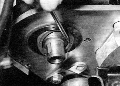
Pic. 16.12. Removal of the right cuff of a camshaft
13. Clean the cuff housing and the sealing surface of the camshaft.
14. Dip a new oil seal in clean engine oil and carefully fit it over the end of the camshaft, open end facing out. A piece of thin plastic or adhesive tape wrapped around the front end of the camshaft helps prevent damage to the oil seal when it is installed.
15. Insert the cuff into the body so that it is flush with the end surface of the cylinder head. To press the cuff into place, use the M10 bolt (screwed into the end of the camshaft), washers, and a suitable piece of machined pipe or socket.
16. Install the toothed pulley on the camshaft as described in paragraph 7.
17. If applicable, install a new timing belt as described in paragraph 7.
Left O-ring
18. The cuff on the left end of the camshaft is missing. Sealing is provided by an O-ring mounted on the vacuum pump flange. The O-ring can be replaced after unscrewing the bolts and removing the pump from the cylinder head (see chapter 9). Notice the smaller o-ring that seals the oil supply gallery to the pump. If it deteriorates and falls out, it may leak through the pump/cylinder head mating surfaces (pic. 16.18).
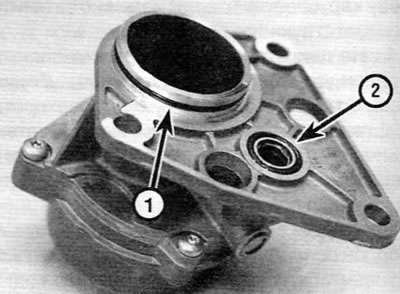
Pic. 16.18. Left cuff camshaft (1) and sealing ring of the oil supply gallery (2) on the back of the brake vacuum pump