



Removal
1. Remove the cylinder head cover as described in paragraph 4.
2. Remove the camshaft timing pulley as described in paragraph 8.
3. Remove the brake system vacuum pump as described in chapter 9.
4. The camshaft bearing caps must be numbered starting from the flywheel end of the engine (figure 11.4). If the caps are not numbered, identify them starting from the flywheel side and mark the side facing the manifold.
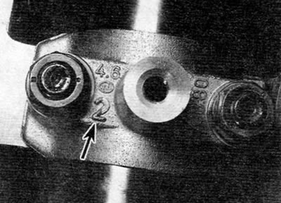
Figure 11. 4. Identification mark (marked with an arrow) on the camshaft bearing cap
5. Gradually loosen the nuts and then remove the bearing caps.
6. Remove the camshaft from the cylinder head. Remove the cuff from the end of the camshaft where the timing belt is located. Discard the cuff and use a new one when installing.
7. Prepare eight small, clean plastic containers and number them 1 through 8. Alternatively, divide the large container into eight compartments. Using a rubber suction cup, remove each plunger one by one and place them in the provided containers. Do not mix up the tappets, this may lead to accelerated wear. If necessary, also remove the adjusting shim from the top end of the valve stem and store it along with the corresponding tappet. Be aware that the adjusting shim may stick to the inside of the tappet when removing it. In this case, be careful that it does not fall out when removing the pusher.
Inspection
8. Inspect the working surfaces of the camshaft and camshaft bearings for signs of wear and scoring. If any of these conditions exist, replace the camshaft. Check the condition of the bearing surfaces on the camshaft journals and in the bearing caps/cylinder head. If the bearing surfaces in the cylinder head show excessive wear, the cylinder head should be replaced.
9. Inspect the surfaces of the tappets that contact the camshaft lobes for wear and scoring. Replace the tappet if this condition exists. If the tappet running surface is heavily scratched, also inspect the corresponding cam lobe on the camshaft for wear, as both elements will likely be worn. Replace the required elements if necessary.
Installation
10. To prevent any possibility of the valves contacting the pistons when installing the camshaft, remove the locking rod/drill from the flywheel and rotate the crankshaft a quarter turn in the direction opposite to the normal direction of rotation to position all pistons at mid-stroke. Remove the timing belt from the high pressure fuel pump sprocket while turning the crankshaft.
11. Install the adjusting shims (if they were removed) on the upper ends of the valve stems, following the original position. Do not mix up the adjusting shims, as this will cause the valve clearances to be out of adjustment (see paragraph 12).
12. Generously lubricate the holes for the hydraulic tappets in the cylinder head and the tappets themselves. Carefully insert the tappets into the cylinder head mounting holes, ensuring that each tappet is installed in its original hole. Some care will be required to insert the pushers into the holes without skewing.
13. Lubricate the camshaft journals and cams with clean engine oil of the prescribed grade.
14. Install the camshaft into the cylinder head by passing it through the front plate of the engine.
15. Temporarily install the timing pulley onto the end of the camshaft and rotate the shaft so that the mounting hole in the timing pulley is aligned with the corresponding cutout in the cylinder head. Remove the toothed pulley.
16. Install the center bearing cap as noted during removal, then install the nuts and tighten them two or three turns.
17. Apply sealant to the outer bearing caps in the locations shown (figure 11.17). Place them in the correct position and tighten the nuts two or three turns.
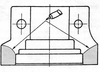
Figure 11.17. Apply sealant to the outer camshaft bearing caps in the locations shown
18. Gradually tighten all nuts to the specified torque, ensuring that the camshaft remains in the correct position.
19. Make sure that the axial clearance of the camshaft corresponds to that specified in "Specifications", using a fan-type feeler gauge. If the clearance is incorrect, the camshaft and/or cylinder head should be replaced. To check the axial clearance, push the camshaft fully toward one end of the cylinder head and insert a feeler gauge between the thrust surfaces of one of the camshaft lobes and the bearing cap (figure 11.19).
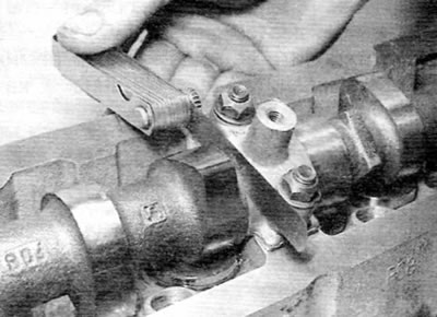
Figure 11.19. Checking the axial clearance of the camshaft using a fan-shaped feeler gauge
20. If the removed camshaft is replaced and the valve clearances are confirmed to be within specification, proceed to the next step. Otherwise, check and adjust the valve clearances as described in paragraph 12.
21. Lubricate the sealing lips of the new oil seal with clean engine oil and place the oil seal on the end of the camshaft so that the sealing lip faces inward. Press the seal until it is flush with the end surface of the camshaft bearing cap.
22. Install the brake system vacuum pump as described in chapter 9.
23. Temporarily install the timing pulley back onto the end of the camshaft and ensure that the locating hole in the timing pulley is aligned with the corresponding cutout in the cylinder head.
24. Turn the crankshaft a quarter of a turn in the normal direction of rotation so that pistons No. 1 and 4 return to the TDC position.
25. Insert the rod/drill into the mounting hole in the flywheel.
26. Install the camshaft timing pulley as described in paragraph 8.
27. Install the cylinder head cover as described in paragraph 4.