



Table of contents: Timing pulley of the camshaft 🠇 Crankshaft toothed pulley 🠇 Toothed pulley of the high-pressure…🠇 Coolant pump toothed pulley 🠇
Timing pulley of the camshaft
Removal
1. Remove the upper timing belt covers as described in paragraph 6.
2. Now you should loosen the camshaft toothed pulley mounting bolt. When unscrewing the toothed pulley mounting bolt, the camshaft must be held from turning, and this can be done in one of two ways, as described below (figure 8.2, a, b). Do not remove the camshaft timing pulley mounting bolt at this stage.
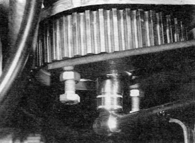
Figure 8.2, a. Using a homemade tool, hold the camshaft toothed pulley from turning
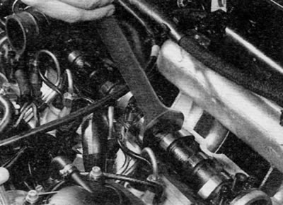
Figure 8.2, b. Hold the camshaft with a wrench by the rectangular section between cams No. 3 and 4
a) Make a tool similar to the one shown and use it to hold the toothed pulley using the holes in the toothed pulley.
b) Remove the cylinder head cover as described in paragraph 4. Prevent the camshaft from turning by holding it with a suitable spanner on the rectangular section between cams No. 3 and 4.
3. Align the engine/timing assembly alignment holes as described in paragraph 3, and lock the camshaft timing pulley, fuel injection pump timing pulley and flywheel. Do not attempt to crank the engine with the locking rods installed.
4. Loosen the timing belt tensioner shaft mounting nut and adjusting bolt, then turn the tensioner bracket counterclockwise to release the tension and tighten the adjusting bolt again to hold the tensioner in the released position. To turn the tensioner bracket against the spring force, use a 10mm square head ratchet, inserted into the provided hole. Remove the timing belt from the timing pulley.
5. Unscrew the previously loosened camshaft toothed pulley mounting bolt and remove it together with the washer.
6. Loosen the camshaft timing pulley lock bolt in the TDC position.
7. Remove the timing pulley from the end of the camshaft (figure 8.7). If the dowel pin on the back of the timing pulley is loose, remove it and store it in a safe place. Inspect the camshaft oil seal for signs of oil leakage and replace it if necessary as described in paragraph 16.
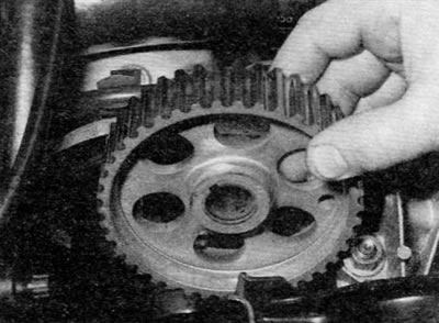
Figure 8.7. Removing the camshaft timing pulley
Installation
8. If applicable, install the woodruff key onto the end of the camshaft and then install the camshaft timing pulley. Please note that the toothed pulley can only be installed one way (protruding central hub to the camshaft), because the end of the camshaft is conical.
9. Screw in the toothed pulley mounting bolt (don't forget to install the washer). Tighten the bolt to the specified torque, preventing the camshaft from turning as during removal.
10. If applicable, install the cylinder head cover as described in paragraph 4.
11. Align the holes in the camshaft timing pulley and the engine front plate and install the 8mm bolt to lock the camshaft.
12. Place the timing belt on the high pressure fuel pump toothed pulley (if applicable) and the camshaft sprocket and tension the timing belt as described in paragraph 7.
13. Install the upper timing belt covers as described in paragraph 6.
Crankshaft toothed pulley
Removal
14. Remove the crankshaft pulley as described in paragraph 5.
15. Proceed as described in step. p. 3 and 4.
16. Remove the timing belt from the crankshaft timing pulley and remove the timing pulley from the end of the crankshaft (figure 8.16).
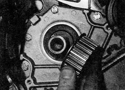
Figure 8.16. Removing the crankshaft toothed pulley
Original is contained on the portal (PEUGEOTBOOK.ru)
17. Remove the woodruff key from the groove on the crankshaft and store it in a safe place along with the toothed pulley (figure 8.17).
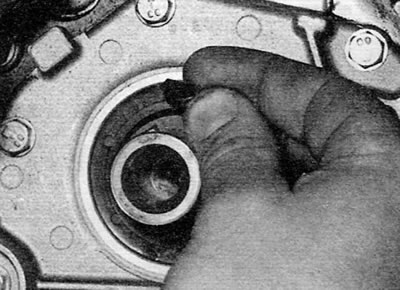
Figure 8.17. Removing the woodruff key from the end of the crankshaft
18. Inspect the crankshaft oil seal for signs of oil leakage and replace it if necessary as described in paragraph 16.
Installation
19. Install the woodruff key into the groove at the end of the crankshaft, and then install the crankshaft timing pulley (flange towards the cylinder block).
20. Place the timing belt on the crankshaft toothed pulley and tension the timing belt as described in paragraph 7. Install the timing belt covers as described in paragraph 6.
21. Install the crankshaft pulley as described in paragraph 5.
Toothed pulley of the high-pressure fuel pump
Removal
22. Perform the actions described in paragraph. p. 1, 3 and 4.
23. Apply relative position marks to the high pressure fuel pump sprocket and timing belt to ensure the sprocket and timing belt are correctly aligned during installation.
24. Remove the 8 mm bolts securing the high-pressure fuel pump toothed pulley in the TDC position.
25. On some models, the timing pulley may be equipped with a built-in puller, which is a plate bolted to the timing pulley. The plate contains a nut (toothed pulley fastening nut), which is screwed into the shaft of the high-pressure fuel pump. On models not equipped with a built-in puller, a suitable puller can be made from a short metal plate and two M7 bolts, which are screwed into the holes provided in the toothed pulley.
26. The shaft of the high pressure fuel pump must be held from turning when unscrewing the toothed pulley nut, and this can be achieved using a tool similar to the one shown (figure 8.26). Use a tool to hold the timing pulley by the holes provided in the pulley.
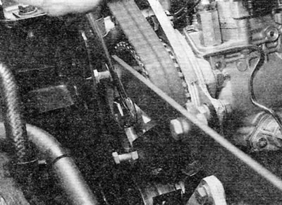
Figure 8.26. Use a homemade tool to prevent the high-pressure fuel pump sprocket from turning
27. On models with a built-in puller, loosen the toothed pulley retaining nut until the toothed pulley is clear of the taper on the pump shaft, then remove the toothed pulley. Remove the woodruff key from the slot on the end of the pump shaft if it is not secured. If desired, you can remove the puller assembly from the toothed pulley by unscrewing two screws and removing them together with the washers.
28. On models not equipped with a built-in puller, partially loosen the toothed pulley mounting nut, then install the homemade puller and tighten the two bolts (pulling the bar towards the toothed pulley nut) so that the toothed pulley comes off the cone on the pump shaft (figure 8.28). Remove the toothed pulley and remove the woodruff key from the groove on the pump shaft if it is not secured. Remove the puller from the timing pulley.
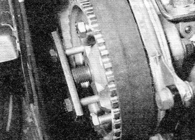
Figure 8.28. Homemade puller installed on the toothed pulley of the high-pressure fuel pump
Installation
29. If applicable, install the woodruff key into the groove on the pump shaft, ensuring that it is properly positioned in the groove.
30. If the built-in puller (if available) was removed from the toothed pulley, install it and tighten the two screws to the specified torque. Don't forget to install the washers.
31. Install the toothed pulley, then tighten the nut to the specified torque, holding the pump shaft from turning as during removal.
32. Ensure that the 8mm diameter bolts are inserted into the camshaft and high pressure fuel pump sprockets and that the rod/drill is inserted into the mounting hole in the flywheel.
33. Place the timing belt on the high pressure fuel pump toothed pulley, ensuring that the marks made on the belt and toothed pulley are aligned before removal.
34. Tighten the timing belt (see paragraph 7).
35. Install the upper timing belt covers as described in paragraph 6.
Coolant pump toothed pulley
36. The coolant pump toothed pulley is integrated with the pump and cannot be removed.