
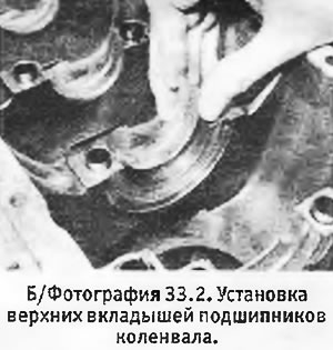
2. Wipe clean the main bearing seats in the crankcase and reinstall the upper bearing shells. These bearings have an oil groove (unlike the lower liners that are in the covers). Check that the mounting tabs of the bushings fit securely into their slots in the crankcase. If you have not replaced the earbuds, make sure they are in their original positions. After installation, lubricate the liners well with clean engine oil (see photo).
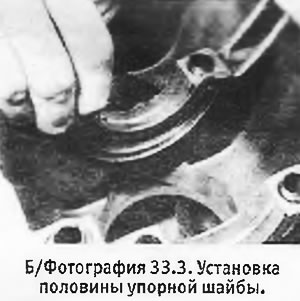
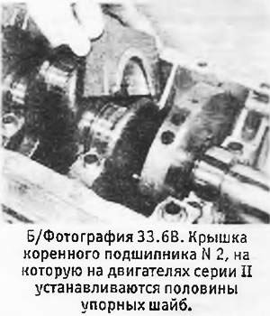
3. Install the halves of the thrust washers on the bearing N 2 grooves towards the crankshaft (see photo).
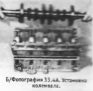
4. Check that the crankshaft is absolutely clean and carefully lower it into the crankcase on the main bearings (see photo).
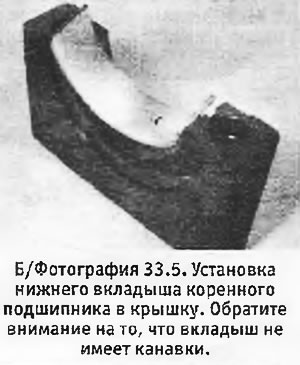
5. Check that the main bearing caps are clean and install the lower bearing shells into them (see photo). And in this case, if you did not replace the liners, they should go to their original places. On series II engines, two more halves of the thrust washers must be installed on the main bearing cap No. 2 so that their grooves look at the crankshaft.
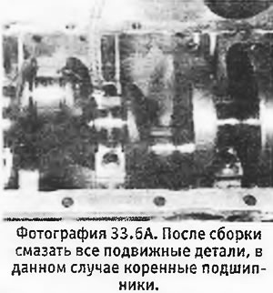
6. Check that all centering shoulders of the main bearing caps are in place in the crankcase, lubricate the bearings with oil and install the caps on their bearings (All caps are numbered from the clutch side) (see pictures).
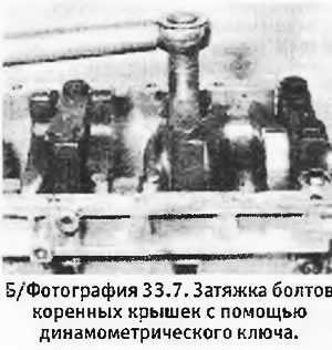
7. Install new washers on the 10 cover mounting bolts. If the holes in the crankcase for the cover bolts are not "blind", i.e. pass through, a thread locking compound should be applied to the threads of the bolts. If holes "blind", it is not necessary to apply the composition. Insert the bolts and tighten them to the correct torque (see photo).
8. Check the axial movement of the crankshaft. On Series I engines with thrust washers in the crankcase only, this check can actually be done before the main bearing caps are installed. On Series II engines that have thrust washers in both the crankcase and the main cover, replace the covers before checking crankshaft axial movement. Move the crankshaft to one side until it stops and use feeler gauges to measure the gap between the thrust washers and the surface of the crankshaft (see pictures). The clearance must not exceed the limits specified in Specifications.
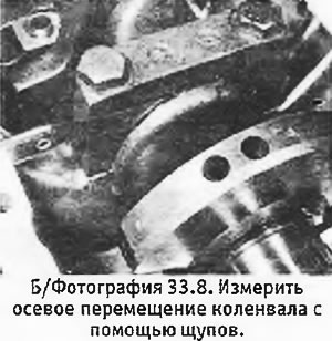
If it goes beyond them, it is necessary to select new thrust washers that would provide the required clearance. Note that all thrust washers must be the same thickness. After obtaining the desired axial movement, turn the crankshaft and check it for freedom of rotation.