
2. Turn the cylinder block over and install the upper main bearing shells. Install the thrust washer segments on the bearing N 2 with the grooved side facing out (see photo) and fix them in place with grease. Please note that the recommended location of the grooved (G) and conventional (R) bearing shells varies depending on the model:
Early models (up to N 9 207 534)
| Bearing N | 1 | 2 | 3 | 4 | 5 |
| Top liner | R | G | R | G | R |
| Bottom liner | R | R | R | R | R |
Latest Models (with N 9 207 535)
| Bearing N | 1 | 2 | 3 | 4 | 5 |
| Top liner | G | R | R | R | G |
| Bottom liner | G | R | R | G | G |
3. Lubricate the bearing shells with oil and lower the crankshaft into place, being careful not to dislodge the thrust washer segments (see photo). Inject some oil into the oil passages of the crankshaft.
4. Install the side seals on the N 1 main bearing cap. Carefully replace the cap with the bearing shell and lubricate the shell, side surfaces of the cap and the mounting surfaces in the cylinder block. There is a risk of displacement or deformation of the side seals during installation of the cover, therefore they should be protected with feeler gauges or tin strips that can be pulled out after installation of the cover (see pictures).
5. Install the liners in the remaining main covers, lubricate them with oil and install the covers in place. Install the thrust washer segments on cover no. 2 with the grooved side facing out. When assembling, follow the alignment marks made during disassembly. The protrusion on the main covers should look towards the timing gear sprockets.
6. Install the main cap nuts and bolts and tighten them to the correct torque. Tighten the side bolts on the bearing cap N 3 last (see photo).
7. Check the amount of protrusion of the side seals of cover N 1 above the contact surface of the pallet. Seals must protrude 2 mm (they can be cut as needed).
8. Check the axial movement of the crankshaft (see chapter 1A, section 33, paragraph 8).
9. Lubricate the lips of the new oil seal and install it with the lips inward on the end of the crankshaft on the flywheel side. Drive the gland into place with a tube (see photo).
10. Install the key and oil pump drive sprocket on the crankshaft toe. Put a chain on the sprocket (see pictures).
11. Check that the locating pin is in place, engage the chain with the sprocket and bring the pump to its installation location on the cylinder block. Put the pump on the mounting pin and then lift it up so that you can insert a spacer under it, which looks like a corner (see pictures).
12. Insert the oil pump mounting bolts, remembering that the special centering bolt is closest to the flywheel, and tighten them to the desired torque. Lubricate the pump and chain well (see photo).
13. Install the pulley oil seal housing on the contact surface of the cylinder block using silicone sealant. Install a new oil seal with lubricated sponges inside and hammer it into place with a tube.
14. Install the pallet with a new gasket and gradually tighten its fixing bolts to the desired torque. Be sure to install the three hex bolts correctly.
15. Install the suction drain tube with a new O-ring. Be careful not to overtighten the fixing nuts - the maximum allowable tightening torque is 0.5 kgm.
16. Install the flywheel on the crankshaft flange and secure it with new bolts, lubricating their threads with a compound for fixing threaded connections. Gradually tighten the bolts to the correct torque.
17. Install the driven disc and clutch basket.
20. Install the assembled cylinder head so that it sits on the pins.
21. Insert the head bolts after cleaning and oiling their threads. Don't forget to install a spacer under the water pump.
22. Gradually tighten the bolts in sequence from the torque specified for step 1.
23. Loosen bolt No. 1 and then tighten it to the torque indicated for step 2. Tighten it additionally to the angle indicated for step 3. Repeat this operation for the remaining bolts in the correct sequence.
24. Install the camshaft sprocket support shield, insert a 10 mm bar into the mounting hole to block the shield, and tighten the shield mounting bolts.
25. Install the camshaft sprocket, washer and bolt. Insert a 10 mm bar into the mounting hole to lock the sprocket in the correct position and tighten the bolt to the correct torque. Pull out the rod.
26. Install the engine support bracket and tighten its bolts (see photo).
27. Install and secure the water pump with a new gasket. Tighten the pump bolts to the correct torque.
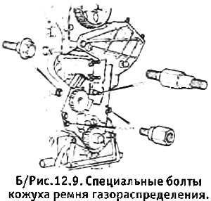
28. Install the timing case parts around the water pump, paying attention to the position of the various special bolts (see fig. 12.9).
29. Install the key and crankshaft sprocket.
30. Install the camshaft drive belt tensioner without tightening its nuts yet.
31. Temporarily install the crankshaft pulley, its washer and bolt and lightly grab the bolt. Carefully turn the crankshaft so that a 10 mm diameter bar can pass into the mounting hole in the pulley and then into the special recess. If there is contact between the piston and the valve, immediately turn the crankshaft back and try again to insert the rod with a slightly different camshaft position. Do not try to force the crankshaft if the piston is in contact with the valve.
32. Block the camshaft sprocket with a bar with a diameter of 10 mm, remove the crankshaft pulley and install the camshaft drive belt. Be careful not to twist the belt and pay attention to the arrows indicating the correct direction of rotation. The two white stripes on the belt should line up with the timing marks on the sprocket.
33. Pull out the rod and tighten the belt by turning the tensioner cam so that it looks down. Lock the cam in this position with a lock nut. Tighten the 2 nuts at the front of the tensioner.
48. Turn the crankshaft 2 full turns in the normal direction of its rotation and then turn it further so that the pistons NN 1 and 4 are in the TDC position. and the valves of cylinder No. 1 were open.
34. Loosen the two nuts and the cam locknut on the drive belt tensioner and then tighten them again.
35. Temporarily install the crankshaft pulley, rotate the crankshaft and check that the bars can be inserted into the crankshaft pulley and camshaft sprocket mounting holes at the same time. If not, remove the belt and try to reinstall it. Remove pulley.
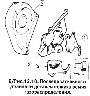
36. To establish a casing of a driving belt in the sequence shown in fig. 12.10. (Please note that the cover will have to be removed to tension the drive belt if you installed a new belt).
37. Install the crankshaft pulley, washer and bolt, making sure the key is still in place. Lock the starter ring gear and tighten the bolt to the correct torque.
38. Install the valve cover with a new gasket, paying attention to the copper washer of the bolt on the side of the camshaft sprocket.
39. Install the accessories listed below (the installation of the generator and distributor can be postponed until the time when the engine is delivered to the machine):
- A. Oil filler pipe/crankcase breather pipe (see photo)
- b. Oil pressure switch
- V. Inlet pipe and inlet housing of the cooling system (see photo)
- d. Spark plugs, distributor and high voltage wires
- e. Generator with drive belt.
40. Install a new oil filter, lubricate its O-ring well, and tighten the filter by hand.