
2. Turn the cylinder block upside down and check that the liner seats are absolutely clean. The slightest trace of dirt in the sockets can cause the head gasket to leak over time. If you have not replaced the cases, they must be reinstalled in their original locations, following the marks made during disassembly. Check that the sleeves are clean and that there are no dirt, traces of old sealant, etc. on their lower surfaces.
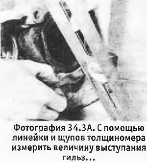
3. Insert the sleeves into the block (so far no pads) and using a dial gauge, measure the amount of their protrusion above the upper surface of the cylinder block. For each sleeve, measurements are made at 4 points spaced 90°apart from each other. In the absence of a dial gauge, you can use the ruler and feeler gauges (see photo).
 |  |
4. All 4 numbers obtained for each sleeve must be the same: if they differ from each other by more than 0.02 mm, then the sleeve is skewed.
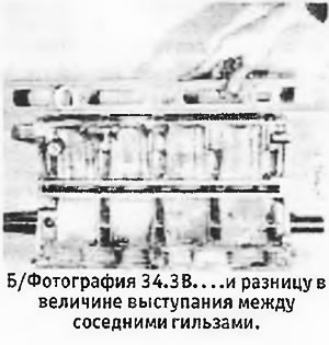
5. Choose for each sleeve a gasket of the required thickness, which would ensure the correct protrusion of the sleeve over the block. In this case, the difference in the amount of protrusion between adjacent sleeves should also not go beyond the specified limits. No more than one spacer may be used for each sleeve. If problems occur, check to see if there is dirt between the sleeve and the block, and how accurately you made the measurements. New sleeves can be interchanged in the block. If you still cannot get the desired result, it is possible that the sleeves are deformed and should be taken to a specialist for inspection.
6. After selecting the gaskets for all liners, install the liners with gaskets in the cylinder block and again check the amount of protrusion and the absence of distortions (see section 8).
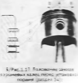
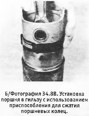
7. If you did not replace the pistons, they should be installed in the original sleeves, using the marks made during disassembly. Before installing the piston in the sleeve, the piston ring locks must be correctly positioned. The lock of the expander of the lower oil scraper ring should be located immediately above the axis of the piston pin, and the locks of the thin rings that make up the oil scraper ring should be shifted 20-50 mm in different directions from the expander lock (see b/fig. 1.17). The locks of the middle and upper compression rings must be displaced by 120°in opposite directions from the expander's lock.
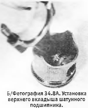
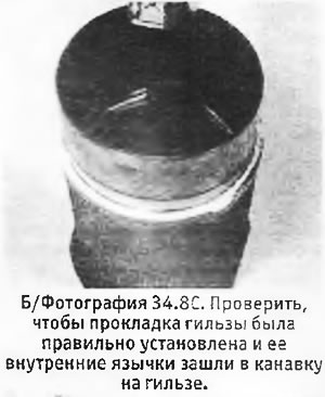
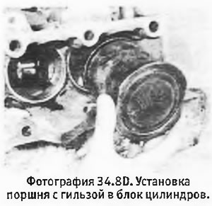
8. Clean the bearing seats in the lower connecting rod heads and install the lower connecting rod bearing shells into them (see photo). Lubricate the inside of the liners with clean engine oil and, using a suitable piston ring compressor, insert the first piston with the connecting rod into its sleeve (see photo). Check that the liner gasket is properly installed and insert the liner into the block while guiding the connecting rod towards the crankpin (see pictures). Check that the sleeve is correctly inserted into the block and the piston is correctly inserted into the sleeve. Old parts must have marks made during disassembly, and these marks must be aligned. If you install new cases, mark them according to their position.
 |  |
 |  |
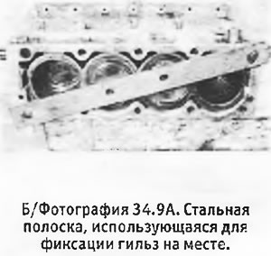
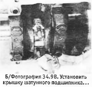
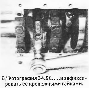
9. After installing all the liners with connecting rod and piston groups, fix the liners with special metal strips so that they do not move during the installation of the connecting rod caps (see photo). Wipe clean and dry the covers and install the lower connecting rod bearing shells in them. Lay out the covers in order and install them on the connecting rods, having previously well lubricated the connecting rod journals and bearing shells with clean engine oil (see photo). Check that the alignment lugs on the bearing shells mate on the same side. Install the connecting rod cap retaining nuts and tighten them to the correct torque (see photo).
 |  |
10. Check the crankshaft for freedom of rotation.