
1. Make sure all parts are clean.
2. Lubricate all moving parts with a thin layer of grease. Lubricate these parts before installing them, and not after, because the grease in this case will not get on the mating surfaces. Be sure to lubricate the pistons, piston rings and cylinder walls well with engine oil.
3. Thoroughly clean all parts of the cylinder block if the engine has been completely disassembled. When cleaning parts of a partially disassembled engine, be careful not to get dirt or foreign particles on the removed parts and open engine openings. For this reason, it is recommended that all openings be closed or sealed.
4. Blow out oil passages and holes with compressed air. If this is not possible, then clean these holes with a wooden pin. Never clean holes with metal objects.
5. Replace oil seals, seals, etc. without fail. Don't skimp on these parts and don't install used ones.
6. Use the specifications for wearing parts. In the event that any part is in doubt, it is recommended to replace it with a new one in order to avoid re-engine overhaul.
7. Purchase replacement parts only from an authorized dealer, and include the engine number.
Before assembling a disassembled engine, it is necessary to check the height of the protrusion of the cylinder liners if these are XU7 engines. Round gaskets are installed at the base of the sleeves of these engines, which do not affect the size of the protrusion. As a rule, the dimensions of the protrusion of the sleeves always correspond to the stern, however, this operation should be carried out as a means of control.
XU10 engines - assembly
8. Turn out carving plugs of oil apertures to clean these apertures during cleaning of the block of cylinders. Plugs are on the back of the block (plug tightening torque 48 Nm) and on the end side (tightening torque - 25 Nm). A socket wrench is required to unscrew the plugs.
9. Fix the block of cylinders on the assembly stand and establish on a workbench so that it was possible to put the top loose leaves of bearings. The liners are the same, so they must be installed in accordance with the marks made when disassembling the engine. In the process of fine-tuning the engine, the bearing clearance was reduced. For this reason, it is recommended to find out by contacting the appropriate workshop whether your car's engine has been affected by such a change. The bearing clearance is reduced by installing four different-sized bushings in the bearing caps instead of one. The main bearing shells installed in the cylinder block have the same size and lubrication grooves. The crankshaft of the engine with four liners in the bearing caps has a corresponding designation. A similar designation is applied to the cylinder block. On engines with reduced bearing clearance, the oil pump drive has also been changed (see illustration).
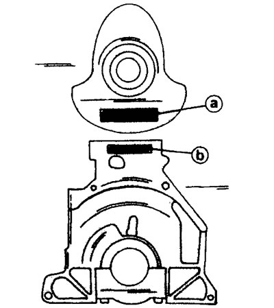
5.9 Crankshaft marking «a» and cylinder block «b» for engines with reduced main bearing clearance
10. Lubricate the liners inserted into the sockets of the cylinder block, making sure that they all have an oil groove (groove). Also lubricate the main bearing journals and connecting rod journals and place the crankshaft in the cylinder block. Rotate the shaft several times to install the liners.
11. Install on the second bearing, counting from the back of the engine, both thrust half rings to adjust the axial play of the crankshaft. The oil grooves must face the crank arm (see illustration).
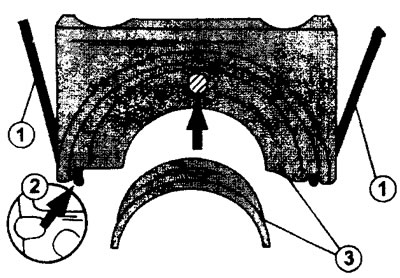
5.11 Fitting the bearing cover.
1 - side sealing rings (gaskets)
2 - guides
3 - marks on the lid and inserts
12. Insert liners without lubrication grooves into the main bearing caps. Insert both remaining half rings into the second bearing cover to adjust the crankshaft end play. Secure the guide tabs in the grooves.
13. Install caps with inserts (and adjusting half rings in the cover of the second bearing) in place in the same order, according to the marks made during removal. At the ends of the covers there are mounting protrusions that must go into the recesses (see illustration 5.11). Install and screw in the bolts of covers 1, 2, 3 and 4.
The bearing cap near the flywheel has side o-rings (see illustration 5.11). A special tool is required to install this cover together with the O-rings and rubber gaskets.
14. Apply sealing compound to the surfaces of the crankcase housing to which the bearing cover will be attached (see illustration).
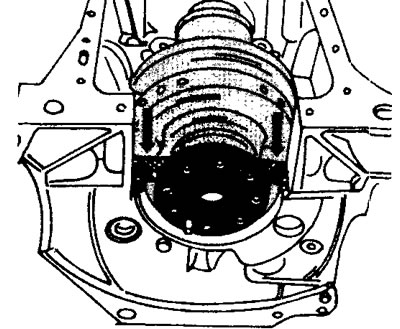
5.14 Apply sealing compound to the surfaces of the crankcase housing to which the bearing cap will be attached (see arrows)
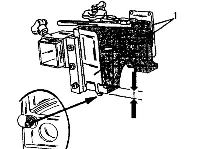
15. Install the bearing cover in the guides of the special tool so that the side seals fit into the grooves. The lower ends of the rings must protrude from the cover by at least I mm (see illustration).
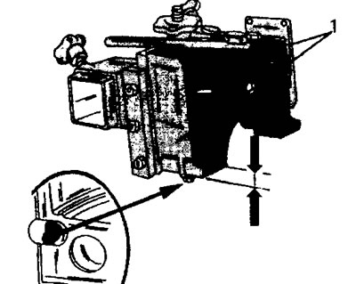
5.15 Fix the bearing cover in the guides 1 of the special tool so that the side seals fit into the grooves. The lower ends of the rings must protrude from the cover by at least 1 mm (see arrows)
Tighten the tool guide bolts by hand.
16. Install the rubber grommets on the bearing cover. These gaskets are precisely sized and do not need to be resized to fit the stop face of the lid.
17. Squeeze the guides of the special tool with your hands and enter the entire structure into the cylinder block at a slight angle until the cover is fully seated in place.
18. Insert the bearing cap bolts into the holes and tighten them by hand.
19. Remove the special adaptation for installation of a back cover of the bearing.
20. Tighten the bolts for all covers, following the sequence and acting from the middle out. The tightening torque of the bolts is 70 Nm (see illustration).
5.20 Tighten the bolts securing all covers, following the sequence and working from the middle to the outside
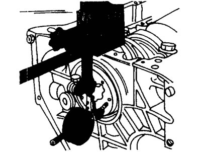
21. Screw two bolts into the crankshaft flange (flywheel bolts) and fasten a screwdriver between them. Rotate the crankshaft with a screwdriver to make sure the crankshaft turns freely and is not stuck anywhere. If there is a jamming of the crankshaft, then find out the cause and eliminate it.
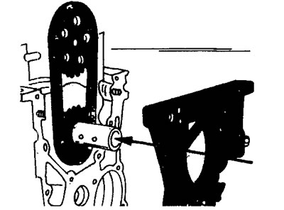
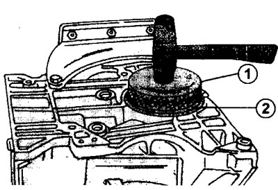
22. Lubricate with engine oil the outside of the new oil seal of the hole on the back of the cylinder block and press it into this hole using a round metal mandrel (see illustration).

5.22 Press a new oil seal 2 into the hole on the back side of the cylinder block using a round metal mandrel 1
23. Arrange the assembled pistons and connecting rods in order of installation. Orient piston ring locks evenly on piston surfaces.
24. Install a mounting sleeve on the piston to install the piston with piston rings in the cylinder and insert it into the cylinder bore well lubricated with engine oil, guided by the marks applied before removal. The sleeve on the piston should sit so that the bottom of the piston comes out from under it. This will force the piston into the cylinder bore. After the piston is inserted into the hole, press it in and remove the mandrel (see illustration).
5.24 Install a mounting sleeve on the piston to install the piston with piston rings in the cylinder and insert it into the cylinder bore. The sleeve on the piston should sit so that the lower part of the piston comes out from under it.
Lead the connecting rod so that it «sat down» on the crank neck. In case of installation of previous liners, do not mix them up. After installing the piston, make sure that the combustion chamber in the piston is turned in the correct direction. This means that the arrow on the piston pin must point in the direction on which the toothed belt is located. Install the piston of the fourth cylinder in the same way.
25. Insert the bearing shells into the bearing caps of both installed connecting rods, guided by the marked marks. Lubricate the bearing surfaces well with engine oil. If the old liners are installed, then they should be put on the same bearings with which they stood before removal. Always replace the connecting rod bearing cap bolt nuts with new ones. Tighten the cover nuts with a torque of 20 Nm. and then tighten by 70°using a goniometer.
26. Rotate the crankshaft so that the journals of the still installed pistons are in the lower position. Install the remaining two connecting rods and pistons on these necks, proceeding in the same way as when installing the first and fourth pistons. After installing these pistons, check again that the crankshaft is not jammed anywhere and it rotates freely.
Axial play of the crankshaft - check
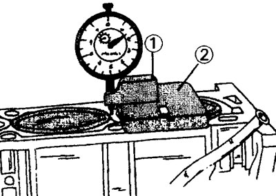
27. Install an arrow-type indicator on the end side of the cylinder block, securing it with an appropriate holder. The indicator pin must rest against the shoulder of the crankshaft (see illustration).
5.27 Install an arrow type indicator on the end side of the cylinder block, securing it with an appropriate holder, to check the axial runout of the crankshaft
If you have an indicator with a magnetic mount, attach the indicator to the shaft so that the indicator pin touches the ground surface of the shaft.
28. Press the crankshaft along its axis in the opposite direction and set the indicator arrow to «0».
29. Press on the crankshaft from the opposite side and read the instrument reading. The reading should be between 0.07 - 0.27 mm. If the obtained reading of the axial play is greater, then it is necessary to install two half-rings of an increased size of the same thickness. In addition to the semi-elbow with a nominal thickness of 2.30, there are thrust half rings with a thickness of 2.35, 2.40, 2.45 and 2.50 mm. Be sure to install half rings of the same thickness.
30. Install the flywheel on the crankshaft. At the same time rotate the flywheel on the shaft until the holes in the flywheel and the flange match. The flywheel bolts must be replaced with new ones. Lubricate the threads of the bolts with protective paste. When tightening the bolts, hold the flywheel against turning with an appropriate stop. All bolts are tightened evenly with a torque of 50 Nm.
31. Fix on a flywheel a conducted disk and a pressure disk of coupling. The longer part of the driven disc hub must face away from the flywheel. Fasten the pressure plate only after the marks on the driven and pressure plates match. A clutch centering rod is required to install the clutch (see section «Clutch»).
32. While holding the flywheel from turning, tighten the pressure plate mounting bolts with a torque of 20 Nm in a cross pattern. When doing this, make sure that the centering rod does not fall out of the hole.
33. Check the runout of the flywheel after it is installed on the crankshaft. Flywheel runout is measured with a pointer-type indicator mounted with the measuring pin touching the surface of the flywheel (see illustration).
5.33 Check the runout of the flywheel after it has been installed. The measuring pin of the indicator must touch the surface of the flywheel
34. Rotate the crankshaft and at the same time follow the indicator arrow. With a full turn of the crankshaft, the deviation of the arrow should not exceed 0.06 mm. Large values indicate the presence of foreign bodies between the flywheel and the crankshaft. If the support pin of the toothed belt tensioner was removed, lubricate the thread of the support pin and screw the pin into the hole on the cylinder head with a torque of 16 Nm.
35. Install the belt tension roller. On engines with two camshafts, install the second belt tensioner in the same way.
36. Fix on the opposite side of the block of cylinders the oil pump. The drive chain and sprocket must be installed as shown in illustration 4.23. Do not forget to install a gasket between the pump and the cylinder block. Tighten the three pump mounting bolts to a torque of 16 Nm. The oil pump mounting bolts vary in length. longest bolt (80 mm) is screwed into the hole on the right side, and the shortest (65 mm) - into the hole on the left side. The length of the remaining third bolt is 70 mm (see illustration).
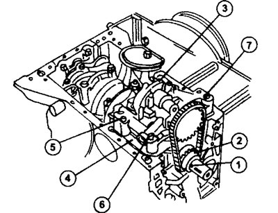
5.36 Installing the oil pump
1 - key
2 - oil pump drive chain
3 - oil pump
4 - gasket
5 - oil pump mounting bolt
6 - oil pump mounting bolt
7 - oil pump mounting bolt
37. Reinstall the front cover of the cylinder block. Before installation, apply a sealing mass to the mating surface of the cover. The cover is fastened with four bolts, including two 40 mm long on top and two 20 mm long on the bottom. The tightening torque of all bolts is 15 Nm (see illustration).
5.37 Reinstall the front cover of the cylinder block. Before installation, apply a sealing mass to the mating surface of the cover
38. Pack a new oil seal into the cover and onto the crankshaft. Lubricate the outer part and the working edge of the oil seal with engine oil and hammer into place using a mandrel or a pipe of the appropriate diameter.
39. Install the oil pump drive chain guard. Bolts of fastening of a casing tighten with the moment of 10 Nm (see illustration).
5.39 Install the oil pump drive chain guard
1 - gasket
2 - oil pan mounting bolts
3 - protective casing of the oil pump drive chain
40. Install the oil pan. There are two options for oil pans. If the car is equipped with air conditioning, apply a sealing mass to the mating surfaces, install the oil pan and tighten the mounting bolts. Do not forget that the pallet mounting bolts have different lengths (see illustration).
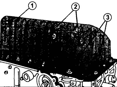
5.40 Installing and securing the oil pan on vehicles with air conditioning 1 - 19 pallet mounting bolts 22 mm long 2 - 2 pan fixing bolts, 40 mm long 3- 2 pan fixing bolts, 20 mm long
Tighten all bolts with a torque of 16 Nm.
If the car does not have air conditioning, then a conventional oil pan is installed. Before installing it, lay a new gasket. It is also possible that the pallet is installed without a sealing gasket. In this case, a sealing mass is applied to the mating surfaces. The oil pan in this case is fastened with 23 bolts, tightened with a torque of 16 Nm. And in this case, the oil pan bolts have different lengths. The bolts installed in the center of the end and sides are 16 mm long. All other bolts are 20mm.
41. Put a new gasket on the cylinder block and secure the coolant pipe by tightening both bolts of its fastening with a torque of 18 Nm.
42. Install a new water pump gasket, secure the water pump with five bolts and tighten them to 15 Nm.
43. Screw a screw plug into the hole opposite the water pump and tighten it with a torque of 48 Nm. This screw plug must be changed every time after unscrewing.
44. Install the engine mount bracket. The bracket is fastened with five bolts tightened with a torque of 60 Nm. Lubricate the threads of the bolts with protective paste «Frenbloc».
45. Fasten the engine oil pressure sensor to the opposite end of the cylinder block with a tightening torque of 25 Nm or screw a threaded plug into this hole with a torque of 32 Nm. The plug, which is placed above the sensor / plug, is tightened with a torque of 25 Nm.
46. Lubricate the O-ring of the new oil filter with engine oil and secure the oil filter to the engine by tightening the bolts tightly. Then tighten the oil filter 3/4 turn by hand.
47. Reinstall the cylinder head following the procedure given for XU 10 engines with 8 or 16 valves (see relevant chapter).
48. Adjust valve clearance on an 8-valve engine (see relevant chapter). To adjust the clearance, it is necessary to install the shaft drive gear on the camshaft. After adjusting the valve clearance, the gear will need to be removed.
49. Press a new oil seal into the camshaft hole on the cylinder head, after lubricating its outer side and working surface with engine oil.
50. Install the drive gear on the camshaft after pressing the gland and secure it with a bolt with a gasket. Tighten the fastening bolt with a torque of 35 Nm. When tightening the bolt, keep the gear from turning with the appropriate tool (see illustration).
5.50 Hold the camshaft gear from turning with the appropriate tool
1 - camshaft gear
2 - gear mounting bolt. Tightening torque 35 Nm
3 - stop to keep the gear from turning
51. Install the toothed belt and tighten it (see relevant chapter). Do not forget that thrust pins will be needed to fix the crankshaft and timing gear. Certain skills are also needed when using a device for tensioning a toothed belt.
52. Install the oil line in the cylinder head and install the cylinder head cover. Tighten the head cover bolts with a torque of 10 Nm (see illustration 4.13).
53. Screw in the spark plugs. The moment of an inhaling of candles is 18 Nm.
54. Install new exhaust manifold gaskets and secure the exhaust manifold with 8 nuts, tightening them to a torque of 35 Nm in a cross pattern.
55. Lubricate the guide tube of the engine oil level gauge with protective paste «Frenbloc» and fix it in the corresponding hole on the cylinder block. Tighten the bolt at the upper end of the guide with a torque of 10 Nm. 61 Install the intake manifold on the opposite side of the cylinder head with a new gasket. Tighten both manifold mounting nuts to a torque of 30 Nm, and four bolts to a torque of 22 Nm.
56. Replace the O-rings and the gasket of the upper thermostat housing bolt with new ones. Tighten all three coolant temperature sensors with a torque of 18 Nm, as well as both bolts of the thermostat housing cover (see illustration).
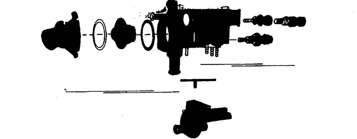
5.56 Parts of the thermostat housing
57. Install the assembled thermostat housing on the cylinder head above the end of the camshaft. Apply a sealant to the mating surfaces of the thermostat housing and cylinder head. Tighten the thermostat housing bolts with a torque of 13 Nm.
58. Perform all other work, proceeding in the reverse order of disassembly.
XU7 engine
59. Measure the protrusion of the working cylinder liners before proceeding with the assembly of the engine. At the base of the liners are round gaskets that do not affect the protrusion of the cylinder liners. The protrusion of the sleeves is almost always correct, but such a check should be carried out as a means of control (see illustration).
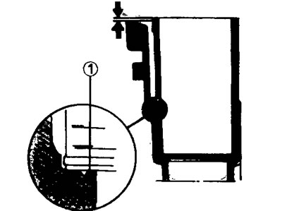
5.59 O-ring 1 at the base of the cylinder liner
Checking the protrusion of the cylinder liners is performed as follows.
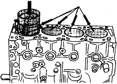
60. Install the cylinder liners without O-rings in the cylinder block.
In this case, the marks on the sleeve and on the piston should be in line, and the arrow on the bottom of the piston should point to the front side of the engine, on which the timing belt is installed (see illustration).
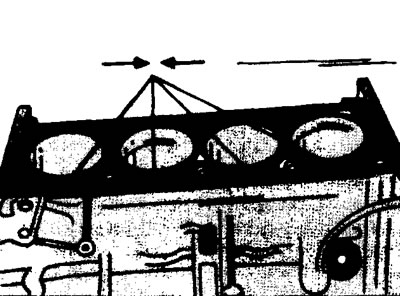
5.60 Install the cylinder liners without O-rings in the cylinder block
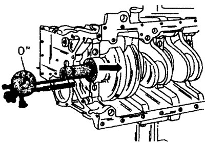
61. Install a dial indicator on a support with a holder and measure the protrusion of each sleeve (see illustration).
5.61 Install a dial indicator on support 1 with holder 2 and measure the protrusion of each sleeve
You can use an appropriate measuring ruler by placing it on the surface of the sleeve and measuring the distance between the ruler and the surface of the cylinder block with a template. First, measure the height of the protrusion of each sleeve individually. After that, determine the difference in the height of the protrusion of two adjacent sleeves. This difference should not exceed 0.05 mm. All sleeves should protrude above the surface of the cylinder block within 0.03 - 0.10 mm. Measure the protrusion of the sleeves on both sides of the sleeve.
If the liner protrusion exceeds the nominal size, then a foreign object between the liner and the liner seat in the cylinder block may be the cause. Remove the sleeve and check the hole. This is also possible when installing new sleeves. In this case, it is recommended to swap the sleeves.
62. Remove the sleeves and install the gaskets. When installing new sleeves, immediately apply the appropriate marks (see illustration 5.60).
Attention! When ordering new O-rings for the base of the cylinder liners, the engine serial number must be specified.
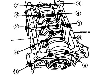
After measuring the protrusion of the cylinder liners, the engine is assembled in the following order. Refer to illustration 5.0 when assembling, which shows the main parts of the crank mechanism.
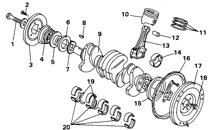
5.0 Crank mechanism
1 - a bolt of fastening of a distributive gear of a cranked shaft. Tightening torque 110 Nm
2 - a bolt of fastening of a belt pulley of a cranked shaft
3 - belt pulley
4 - crankshaft timing gear
5 - spacer washer
6 - stuffing box
7 - oil pump drive sprocket
8 - segment key
9 - crankshaft
10 - piston
11 - set of piston rings
12 - piston pin
13- connecting rod
14 - connecting rod bushings
15 - stuffing box holes on the back side of the cylinder block
16-toothed flywheel ring
17 - flywheel
18 - flywheel mounting bolt
19 - thrust half rings for adjusting axial play
20 - main bearing shells
63. Assemble pistons with connecting rods (see relevant chapter).
64. Install the connecting rod and piston groups in the cylinder liners (see relevant chapter).
65. Insert the pistons together with the liners into the cylinder block and «plant» their. Secure all liners with holders so that the liners or pistons do not slip out of the cylinder block when it is turned over.
66. Install the connecting rod bearing shells in the connecting rods in accordance with the marked marks, if the previous shells are installed. The guide tabs of the bushings must fit into the grooves of the connecting rods.
67. Install the main bearing shells with oil grooves. The guide tabs on the bushings must fit into the grooves. Please note that some of the liners have oil grooves, while the second part of the liners does not. Therefore, when installing, follow the marks made before removing the liners so as not to confuse them in places.
68. Install the adjusting half rings on the second main bearing so that the sliding surface is facing the crankshaft.
69. Lubricate the nested main bearing shells with engine oil and place the crankshaft in the bearings. Use an oil can to lubricate the bearings by rubbing the oil over the surface of the bearings with your finger. Do not use a brush for this.
70. Insert new side seals into the rear main bearing cap and install the cap. The procedure in this case is the same as when installing the rear bearing cap on XU 10 engines (see above).
71. Reinstall all other bearing caps with their inserts. There should be an adjusting semi-ring in the cover of the second main bearing. The bearing caps are numbered and the collar on the cap must face the side where the toothed belt is located.
72. Tighten bolts of covers of radical bearings with the corresponding moment of an inhaling in order.
73. Adjust the axial runout of the crankshaft. The adjustment procedure is the same as for the XU10 engine (see above).
74. Check the protrusion of both side seals on the rear main bearing cap relative to the surface of the cylinder block. The nominal protrusion size is 1.0 mm. The ends of the seals are not cut off. If the length of the protrusion of the seals is greater than the specified length, then the protruding ends do not need to be trimmed. This means that the seals were not installed correctly.
75. Establish covers of rods together with enclosed loose leaves. Follow the marks made during removal so as not to confuse the covers in places if the previous ones are installed.
76. Screw nuts on bolts of covers of rods and tighten them. Tighten on those connecting rods that are at bottom dead center. After that, rotate the crankshaft so that the two remaining connecting rods are at bottom dead center, and tighten the bolts securing their covers.
77. Install the oil pump drive sprocket together with the chain on the crankshaft, after inserting the segment key into the hole.
78. Install the side cover (bearing shield) on the cylinder block from the side of the toothed belt. Apply sealant to mating surfaces prior to installation «Loctite». The top two cover bolts are shorter than the others. Cover bolts tighten with a torque of 16 Nm (see illustration).
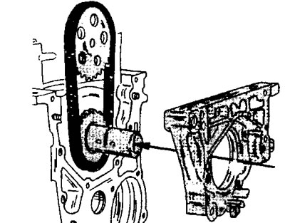
5.78 Install the endshield on the cylinder block
79. Hammer the stuffing box into the hole in the bearing shield. The outer side of the gland must be flush with the surface of the shield.
80. Lay the oil pump drive chain on the pump sprocket and install gaskets on the oil filter side between the oil pump and the cylinder block (see illustration).
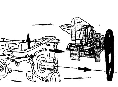
5.80 Lay the oil pump drive chain on the pump sprocket and install the oil pump
Tighten the pump mounting bolts. The bolts on the left side are torqued to 19 Nm and both bolts on the right side are tightened to 13 Nm.
81. Install a new oil pan gasket and secure the oil pan.
82. Reinstall the flywheel. Replace the flywheel mounting bolts with new ones and lubricate their threads with protective grease «Loctite». Use a stop to prevent the flywheel from turning and tighten the flywheel mounting bolts to 50 Nm.
83. Install the driven and pressure plates of the clutch, centering the driven plate on the flywheel using the appropriate rod. Tighten the clutch mounting bolts evenly with a torque of 22 Nm.
84. Install the water pump, replacing its old gasket with a new one and fix it with five bolts with a tightening torque of 15 Nm (see illustration).
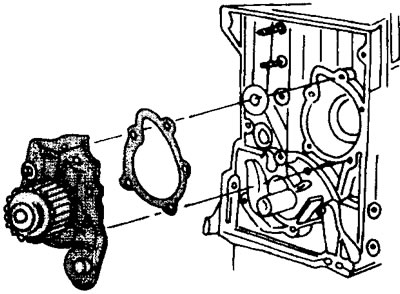
5.84 Install the water pump and secure it with five bolts
85. Install the toothed belt tensioner.
86. Check up landing of both adjusting inserts in the top part of the block of cylinders.
87. Place a dry cylinder head gasket on the cylinder block. At the same time, the marking applied on the left side at the rear of the gasket must face upwards.
88. Install the cylinder head and tighten the bolts of its fastening with the prescribed tightening torques (see relevant chapter).
89. Adjust valve clearance (see relevant chapter).
90. Screw the thermal switch into the thermostat housing and tighten it with a torque of 18 Nm.
91. Install the thermostat in the housing, replacing the two old gaskets with new ones. At the same time, screw the coolant outlet pipe into the thermostat housing.
92. Secure the thermostat housing assembly to the cylinder head by replacing the old gasket with a new one.
93. Remove the toothed belt gear from the camshaft, which was installed to adjust the valve clearance and fill the camshaft oil seal with an appropriate mandrel. Then replace the appropriate cover.
94. Install the timing belt gear onto the camshaft, holding the camshaft from turning.
95. Install the crankshaft and camshafts in the desired position relative to each other, guided by the reference marks, and put on the toothed belt.
96. Install the V-belt pulley on the crankshaft. Hold the flywheel while tightening the pulley bolt to prevent the crankshaft from turning.
97. Follow all steps regarding the fastening of wires, hoses and pipelines. Their installation is carried out in the reverse order of removal.