
Removing
When performing work on the engine, it is necessary to take into account some features, which in turn allow us to conditionally divide all engines into three groups. These are engines without a catalyst, engines with a catalyst and engines with 16 valves. The main specific feature of the engines in each of these groups is the use of an aluminum alloy cylinder block with lubricated cylinder liners (1.8 liter engines) and cast iron cylinder block (2.0 liter engines). A detailed description of all engine versions is not possible.
The power unit is removed from the engine compartment using a hoist, beam or crane. In workshops, when removing the power unit, they also use a lift on which the engine is lowered. To remove the engine in front of the car, it is necessary to install it on the goats and dismantle the elements of the front end. Depending on the car model, minor features of engine dismantling are possible, however, in general, the procedure for removing the engine is as follows.
1. Remove wheel covers.
2. Apply the parking brake and loosen the nuts on the drive shafts (see illustration).
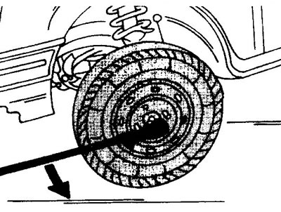
2.2 Loosen the front wheel hub nuts. The vehicle must be on wheels
Do not completely loosen the nuts. The vehicle must be on wheels
3. Disconnect both terminals from the battery terminals.
4. Drain coolant and, if necessary, transmission fluid.
5. Remove the front lining (see illustration).
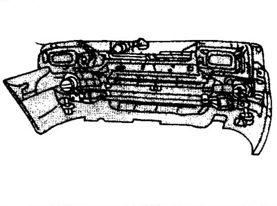
2.5 Remove the front lining
6. Remove the air filter.
7. Remove the grille along with the radiator fan and the radiator itself (see illustration).
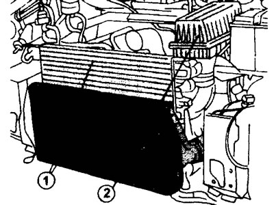
2.7 Remove the radiator grill together with the radiator fan and the radiator itself 1, as well as the air filter 2
Car manufacturers are increasingly using special hose connections and for this reason it may be that the lower radiator hose is connected in this way. The procedure for removing a hose with such a connection is indicated in the relevant chapter (see «Cooling system»). Therefore, if necessary, read the provisions of this chapter. The heater hoses can be connected in the same way.
8. Remove the locking clip of this connection first. After that, use a screwdriver to press the leash to the right and at the same time disconnect both hoses in turn (see illustrations 2.8 and 2.8a).
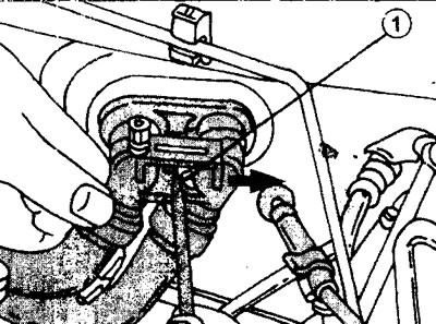
2.8 Remove locking clip 1 (see arrow), to disconnect the heater hoses
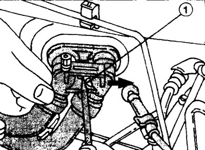
2.8a Remove the locking clip (see arrow), and then with a screwdriver wring out the leash 1 and disconnect both hoses in turn
9. Remove the boost air cooler (intercooler), if the vehicle is equipped with a turbocharger. If the car has air conditioning, then release the compressor and condenser, and then remove them (see illustration). Do not open the air conditioning system.
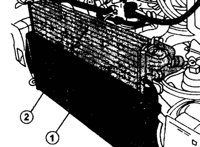
2.9 Radiator 1 charge air (intercooler) turbocharger and condenser 2 air conditioners
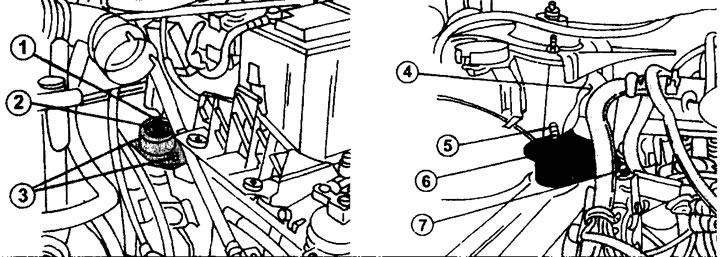
10. Detach the frame cross member (see illustration).
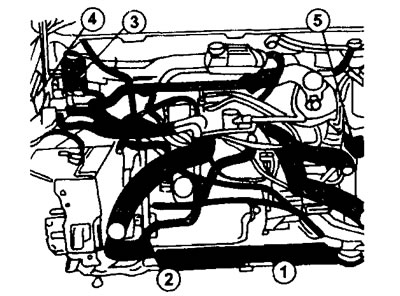
2.10 Disconnect the cross beam 1 of the frame
2 - power steering pump
3 - power steering reservoir
4 - electronic control unit
5 - ABS control unit
11. Turn out bolts of fastening and remove the pump and a reservoir of the hydraulic booster of a steering (see illustration 2.10).
Attention! Do not open the power steering system. Be careful not to get power steering fluid on the paintwork.
12. Remove the electronic control unit, and on the opposite side of the engine compartment - the ABS control unit (see illustration 2.10).
13. Disconnect all hoses, wires and pipelines connected to the power unit. Before that, mark them for later installation.
14. Turn out bolts of fastening of wheels.
15. Install in front of the car on the goats.
16. Disconnect from a transmission the mechanism of a gear change, acting from under the car. At the same time, disconnect the flexible shaft of the speedometer from the gearbox, remove the clamp securing the front pipe to the body and disconnect the lambda probe power wire.
17. Disconnect from a body a regulator of a turbocharger at cars with a turbocharger.
18. Disconnect the wheel drive axles (see relevant chapter).
19. Turn out bolts 2 and 5 (see illustration) and remove the front engine mount bracket. The bolt tightening torques are respectively 65 Nm and 90 Nm.
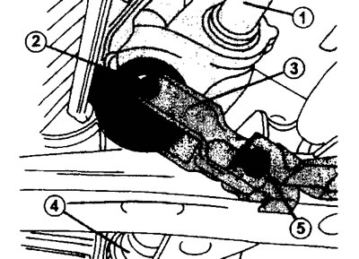
2.19 Remove bolts 2 and 5 and remove bracket 3 of the front engine mount 1 and 4 - drive axles
20. Disconnect all wires from the gearbox (starter wire and reversing light switch wire).
21. Attach the hooks of a hoist or other lifting device to the engine lugs and raise the power unit slightly.
22. Release the supports of the right and left engine and gearbox mounts. To do this, it is enough to disconnect the brackets, and the support pads remain fixed to the body (see illustration).
2.22 Release the supports of the right and left engine and gearbox mounts
1 - nut, tightening torque 80 Nm
2 - engine support cushion
3 - bolts for fastening the engine support cushion, tightening torque 25 Nm
4 - support bolts, tightening torque 65 Nm
5 - nut, tightening torque 45 Nm
6 - right engine mount
7 - support bolts, tightening torque 60 Nm
23. Make sure everything attached to the engine is disconnected. After that, lift the power unit and remove it from the engine compartment. The power unit must be removed from the engine compartment at a certain angle and therefore it should be deployed. Make sure that the power unit does not snag any wires or pipes.
24. Place the power unit on suitable supports, such as wooden beams, and secure it from tipping over.
25. Inspect the power block and make sure that it has no external damage or places with oil or coolant leaks.
26. Clean the engine surface. When doing so, cover any parts that could be damaged during cleaning.