
Thoroughly clean all parts and lubricate all friction surfaces with engine oil.
1. Install the oil seals using a mandrel or a piece of pipe with an inner diameter of 8 mm. Be careful not to damage the caps. Otherwise it will lead to increased oil consumption (see illustration).
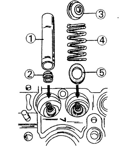
8.1 Installing seals and valves
1 - mandrel for installing oil seals
2 - oil cap
3 - valve disc
4 - valve spring
5 - spring support washer
2. Insert the valves into the guide bushings. If the valves have been ground, they must be installed on the appropriate seats. The same applies to older valves, which must be installed on the same seats on which they stood.
3. Insert the valves, well lubricated with engine oil, into the cylinder head from the bottom side and install the support washers, springs and plates from above (see illustration).
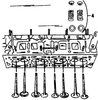
8.4 Valve installation procedure
4. Compress the valve spring with the special tool. Insert the crackers into the grooves on the protruding upper end of the valve stem and carefully release the special tool. Make sure the crackers fit well. The intake and exhaust valve stems are the same. To check the fit of the cotters, hit the top side of the valve stems with a plastic mallet. Crackers that have become incorrectly pop out when struck. Place a rag on the spring to prevent flying parts.
8 valve engines
5. Lubricate the valve tappets and tappet shims with engine oil and install them in their original places. Adjusting washers on one side have rounded edges, the other side is flat, without rounding. It is this side that the shims are installed on the valve stems (see illustration).
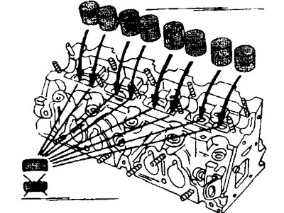
8.5 Lubricate the valve tappets and tappet shims with engine oil and install them in their original places. Adjusting washers are installed with the rounded edges up.
The side with the rounded edges should be facing up.
If you need to check the correct installation of the shims, then the corresponding pusher must be removed completely, because the washer under it at the time of checking can turn over and lie on the opposite side.
6. Lubricate the camshaft bearing journals with engine oil and place the camshaft in the cylinder head. Establish cases of bearings of a camshaft, being guided by the applied labels. Tighten the housing bolts to a torque of 15 Nm, working from the middle to the outside in a cross pattern.
7. Stuff the oil seal into the camshaft hole in the cylinder head after the valve clearance has been adjusted.
8. Install the drive gear on the camshaft and secure it with a bolt, tightening it with a torque of 35 Nm. At the same time, hold the camshaft from turning.
9. Reinstall all other parts of the cylinder head in the reverse order of their removal.
Engine with two camshafts and 16 valves
10 Install the valves and seals.
11. Establish in turn pushers of valves, being guided by the marks put at removal.
12. Lubricate the bearing journals and cams of both camshafts and lay the camshafts in place. Before laying the shafts, also lubricate the bearing surfaces with engine oil. After laying the shafts, make sure they are in the correct position.
13. Turn the left camshaft so that the notch on the mountaineer is facing up and is strictly perpendicular to the horizontal surface (12 o'clock position). The right camshaft must be positioned so that the recess on its end is in line with the reference mark for adjusting the gas distribution mechanism (see illustration).
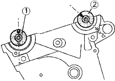
8.13 Mounting position of the camshafts of the engine with 16 valves.
1 - left shaft. The notch at the end was facing upwards and stood strictly perpendicular to the horizontal surface (12 o'clock position).
2 - right shaft. The recess at its end should be in line with the reference mark
14. Be convinced that on corners of a head of the block of cylinders the aligning pins providing the correct installation of a head concerning the block of cylinders are established.
15. Apply sealant to the mating surfaces of the cylinder head and cylinder block. Lubricate the threads of the holes for the cylinder head bolts with the same mass and install the bearing housings.
16. Tighten in two passes, using the diagram, the bolts of the camshaft bearing housings. At the first stage, tighten with a torque of 5 Nm, and at the second - 10 Nm (see illustration).
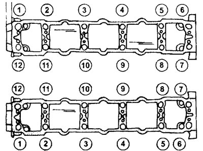
8.16 Bolt tightening diagram for camshaft bearing housings
17. Press the oil seals into the holes for the camshafts. To do this, use a mandrel or ring from a pipe of the appropriate diameter, as well as a bolt with a washer of the appropriate diameter (see illustration).
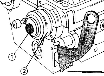
8.17 Pressing the camshaft oil seal into the hole on the cylinder head.
1 - bolt for pressing the stuffing box with a washer
2 - mandrel or ring from a pipe of the appropriate diameter
18. Install on the end side of the engine the parts dismantled during the removal of the cylinder head (see illustration 6.10). bolts (1 and 2) bushing fasteners (3 and 4) tighten the gears of the toothed belt with a torque of 75 Nm. Install stop bolts to keep gears from turning «A».
19. Install the thermostat housing on the opposite side of the cylinder head.
The cylinder head is installed in the order shown above.