
XU engine with 8 valves
1. Install the thrust bolts in the gears of the camshaft and crankshaft (see illustration)
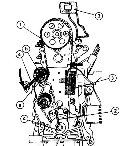
14.1 Features of installing and tensioning the toothed belt using special tools on an XU engine with 8 valves. The letters mark the three main stages of the work
a - turning the belt tension roller
b - tightening the nut
c - turning the crankshaft (two full turns)
1 - thrust bolt of the camshaft drive gear
2 - thrust bolt of the crankshaft timing gear
3 - control and measuring device for measuring the tension of the toothed belt
4 - trunnion (hooked) key
2. Lay the toothed belt as required for this type of engine.
3. Remove the thrust bolt from the camshaft gear.
4. Install the timing belt tension gauge 4122-T as shown in illustration 14.1.
5. Insert a trunnion wrench into the holes on the tension roller to turn it later.
6. Press the toothed belt on the right side inward (in the direction of the arrow, see dotted line in illustration 14.1).
7. Turn the tension roller a of the toothed belt with a trunnion wrench in the direction of the arrow to the left so that the reading on the gauge is 30±2 for XU7 engines or 44±2 for XU10 engines.
8. Tighten bolt b to 20 Nm.
9. Remove the thrust bolt from the crankshaft camshaft gear, remove the control and measuring device, as well as the trunnion key.
10. Rotate the crankshaft two full turns (four engine turns). Re-insert the thrust bolt into the hole on the crankshaft gear and reinstall the gauge.
12. Check that the gauge shows a toothed belt tension of 44±2. This value applies to all engines with 8 valves. In this case, all devices can be removed, and the engine can be assembled. If the reading of the toothed belt tension gauge does not correspond to the specified value, then all work must be repeated from the beginning.
XU10 engine with 16 valves
13. Install the thrust bolts in the holes of the gears of the camshafts and crankshafts, as shown in illustration 14.13.
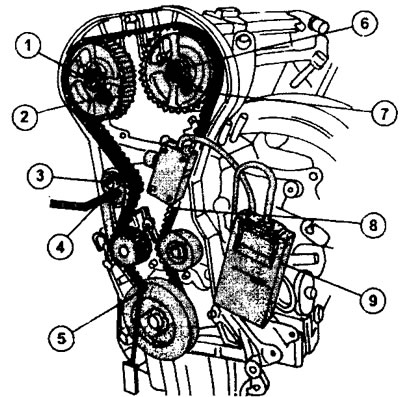
14.13 Features of installing and tensioning the toothed belt using special tools on the XU engine with 16 valves
1 - a bolt of fastening of a drive gear of a camshaft
2 - thrust bolt of the camshaft gear
3 - a bolt of fastening of a roller of a tension of a toothed belt
4 - toothed belt tension roller
5 - thrust bolt of the crankshaft timing gear
6 - a bolt of fastening of a drive gear of a camshaft
7 - thrust bolt of the camshaft gear
8 - toothed belt
9 - control and measuring device
14. Apply the toothed belt in the order given above (see illustration 13.48).
15. Release the toothed belt tension rollers so that they fit snugly against the belt.
16. Establish the control and measuring device for measurement of a tension of a gear belt so as it is shown in an illustration 14.13.
17. Rotate the 3 toothed belt tensioner to the left to obtain a 55 sim belt tension reading on the gauge (see illustration 14.13). A square key is used to rotate the roller.
18. Tighten the bolt 3 of the toothed belt tension roller with a torque of 20 Nm, while preventing the roller itself from turning.
19. Tighten the camshaft gear bolts to 50 Nm. At the same time, keep the gears properly from turning.
20. Remove the control and measuring device and take stop bolts.
21. Turn the crankshaft two full turns (four engine turns) and reinstall the crankshaft timing gear thrust bolt. If after turning the crankshaft the thrust bolt cannot be properly installed, turn the engine two more turns. Never rotate the crankshaft in the opposite direction.
22. Install the gauge again and verify that the gauge confirms the toothed belt tension to 35 sims. If so, then the belt is installed correctly.
23. Tighten bolt 7 to 20 Nm, and the camshaft gear bolts to 75 Nm. If the control and measuring device shows a different value, then all work must be done first. At the same time, reinstall the stop bolts in the holes on the gears of the camshafts and crankshafts so that they do not rotate.