
The principle of operation of hydraulic pushers
Pressurized oil fills chamber A of tappet 1 and from chamber A enters chamber B where the pressure is low. This causes ball valve 4 to open and chamber C to fill.
Piston 2 and sleeve 3 are pushed out by the pressure force of spring 5, thus creating mechanical contact between the cam and the valve stem. A small gap between the piston and the sleeve ensures the ventilation of the pusher (see illustration 9.0).
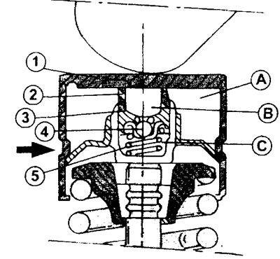
9.0 Hydraulic pusher in section. 16 valve engine
A, B, C - chambers filled with oil
1 - pusher
2 - piston
3 - sleeve
4 - ball valve
5 - spring
When the camshaft rotates, the cam depresses the pusher, thus increasing the oil pressure in chamber C. The ball valve blocks the oil exit from the chamber and the stroke (pressure) the cam is thus transferred to the valve.
If the valve clearance adjustment on an 8-valve engine is performed without removing the engine from the vehicle, then some preparatory work must be done to provide access to the valves. These works include the removal of the air filter and cylinder head (see above).
1. Place the front of the car on the goats and turn on the fifth gear. This will allow the engine to be rotated by turning the wheel.
2. Label the spark plug high voltage wires appropriately and disconnect them from the spark plugs.
3. Turn out spark plugs.
4. Measure the valve clearance and record the data obtained in the form of a plate (see illustration).
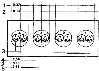
9.4 Valve clearance plate
On this plate it will then be possible to record the values by which the corresponding valve clearance will be corrected
5. Turn the engine in the direction of travel by one of the front wheels. To measure the valve clearance, the corresponding cam must point upwards. This means that the opposite valve of the same cylinder must be open at this moment. Cylinder number 1 is located near the flywheel.
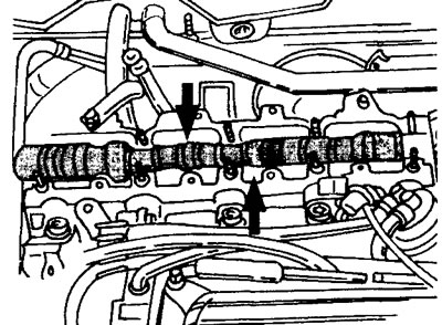
6. Measure the valve clearance using a template by inserting it between the cam and valve lifter (see illustration).
9.6 Measure the valve clearance using a template by inserting it between the cam and valve lifter
7. Record the value obtained in the appropriate column on the prepared plate (see illustration 9.4). In the example shown, the valve clearance was 0.27 mm
8. Turn the engine by the front wheel in the direction of travel for another half a turn and measure the clearance of the next valve. Rotate the motor half a turn each time. before checking the clearance of all valves. Enter the data obtained in the table. The nominal values of the clearance of the intake valves are 0.15-0.25 mm, and the exhaust valves are 0.35-45 mm. If the value obtained by measuring the gap is outside the given nominal tolerances, then the gap must be adjusted by installing shims of a different size between the pusher and the valve stem. If the gap is too large, then thicker shims are installed, with a small gap, thin ones (see illustration).
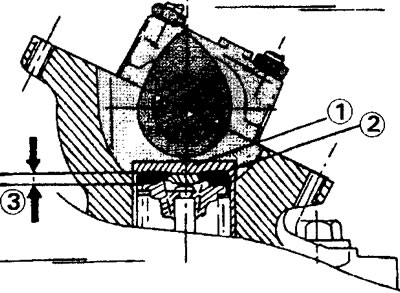
9.8 Camshaft and valve tappet in section
1 - valve lifter
2 - adjusting washer
3 - clearance provided by an adjusting washer of appropriate thickness
If the valve clearance needs to be adjusted, then this requires the dismantling of the camshaft.
9. Disconnect the wire terminal from the battery «masses» (-).
10. Turn away bolts of fastening of the right forward wheel and remove protective inserts of a wheel arch (wheel arch liners), to access the end of the crankshaft.
11. Remove the top part of a protective casing of a gear belt.
12. Insert a thrust bolt into the hole in the belt pulley, which should be at the 11 o'clock position, to lock the camshaft and camshaft timing belt gear.
13. Remove the drive belt from the accessories.
14. Remove the cylinder head and air filter.
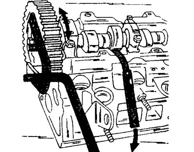
15. Loosen the toothed belt tensioner bolt, move the roller away from the belt and remove the toothed belt from the camshaft gear.
16. Remove the gear from the camshaft. When unscrewing the gear mounting bolt, hold it or turn it.
17. Move the oil line passing over the camshaft to the side (see illustration 9.18).
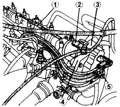
9.18 Remove the parts located at the top of the cylinder head
1 - oil pipeline
2 - coolant outlet pipe
3 - block of ignition coils
4 - holder
5 - high-voltage spark plug wires
18. Disconnect from a head of the block of cylinders an inlet branch pipe of a cooling liquid and the block of coils of ignition (see illustration).
19. Turn out on the forward party of a head of the block of cylinders a bolt with a head under a socket key Mb, and then in regular intervals loosen all nuts of five supports under necks of a camshaft, operating in sequence, the return to a tightening of nuts. Be guided by this (illustration 9.19).
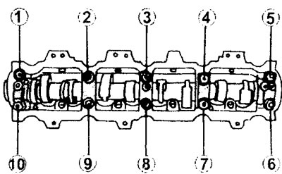
9.19 The sequence of tightening the nuts of the bearings under the camshaft journals. The tightening torque of the nuts is 16 Nm. Loosening and unscrewing the nuts are carried out in reverse order
20. Remove the camshaft and remove the oil seal from the shaft. When installing the shaft, a new oil seal is stuffed.
21. Remove the valve lifter and the shim under the pusher.
22. Measure the thickness of the shim. Due to the fact that these are very small values, the thickness of the washer should be measured with a micrometer. In case of its absence, you can use the arrow type measuring indicator (see illustration).
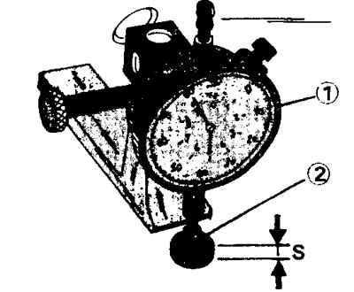
9.22 Measuring thickness S of shim 2 using measuring indicator 1 with pointer indication. In this case, the adjusting washer should be laid on a polished surface
The value of K, by which the gap must be corrected, is determined as the remainder of the deduction of the nominal value of the valve gap O from the value obtained by measuring the valve gap I.
The amount of valve clearance to be adjusted can be positive or negative. If the clearance value is positive, then a thicker shim is installed; if the value is negative, a thinner one is installed. I took into account that the nominal values of the valve clearance are expressed not by one specific figure, but by a whole range of tolerances, then the average value from this range is taken as the nominal value and the thickness of the new shim H is equal to the value obtained when measuring the clearance plus the correction value (H=I+K).
23. Select an adjusting washer whose thickness is as close as possible to or corresponds to the value obtained during the calculation. The thickness of the offered shims is in the range of 2.225-3.550 mm. The step of increasing the thickness is 0.025 mm.
24. Lubricate a new adjusting washer with engine oil before laying it under the pusher. (see illustration).
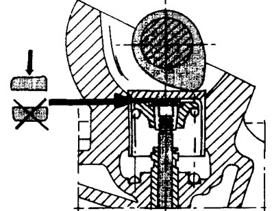
9.24 The rounded side of the shim must face up when installed
Perform the same calculations and actions for the remaining valves whose clearance needs to be corrected.
Attention! If the camshaft or valve tappets were replaced, then the shims are installed with the same nominal thickness - 2.25 mm, regardless of what size washers were before replacing these parts.
25. Lubricate the valve lifters with engine oil and install them in place.
Attention! After installing the pushers, they must not be lifted, because the shim can rise with the pusher, and then lie on the opposite side. If it is necessary to correct the position of the pusher, then it must be removed completely and reinstalled, having checked before that that the adjusting washer is correctly laid.
26. Lubricate the bearings under the camshaft journals and install the camshaft so that the fourth and sixth cams, counted from the flywheel, are adjacent to the corresponding pushers (see illustration).
9.26 The cams must be in contact with the valve lifters
27. Lubricate the mating surfaces of the support located on the side of the toothed belt with sealing mass «Auto Joint» and put the cover on it. After that, replace the covers of the remaining supports in accordance with their numbering.
28. Tighten the cap nuts in the specified tightening sequence, working from the middle to the outside, with a torque of 16 Nm (see illustration 9.19).
29. Pack a new oil seal onto the camshaft. Be careful not to deform the seal. Given that access to the end of the camshaft is difficult, it is recommended to press the oil seal with a mandrel or ring from a pipe of the appropriate diameter, pressing them with a bolt of increased length with a washer of sufficient diameter.
30. Install the driven gear on the camshaft and secure it with a bolt. While holding the camshaft from turning, tighten the gear mounting bolt to a torque of 35 Nm (see illustration).
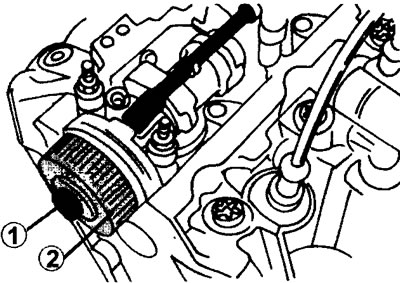
9.30 Installing the driven gear 2 on the camshaft. While holding the camshaft from turning, tighten the gear mounting bolt to a torque of 35 Nm
31. Turn the camshaft at least two turns (So slow) and measure the valve clearance. Adjust the gap if necessary.
32. Reinstall the dismantled parts of the cylinder head, proceeding in the reverse order of their removal. Return the oil pipe to its original position (see illustration 9.18).
33. Install the toothed belt (see relevant chapter).