



Table of contents: Engine DW10 TD 🠇 DW8 Engine 🠇
Engine DW10 TD
When removing and installing the camshaft, Peugeot service centers use the following special tool:
- seal Installation Tool - 0188-N;
- engine Flywheel Fixing Tool - 0188-Y;
- flywheel stopper - 0188-F;
- camshaft locking tool - 0188-M.
Remove the camshaft in the following order:
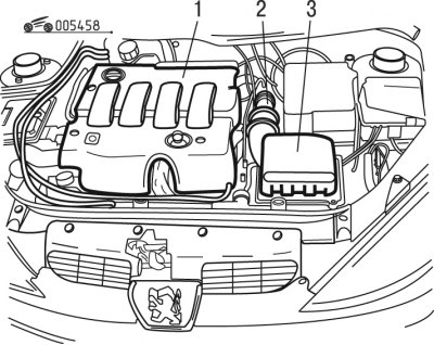
Figure 4.58. Removing engine parts and assemblies: 1 - decorative cover; 2 - node; 3 - air cleaner unit
- remove decorative cover 1 (figure 4.58);
- remove air cleaner assembly 3;
- disconnect and move node 2;
- disconnect the engine crankcase ventilation system tube;
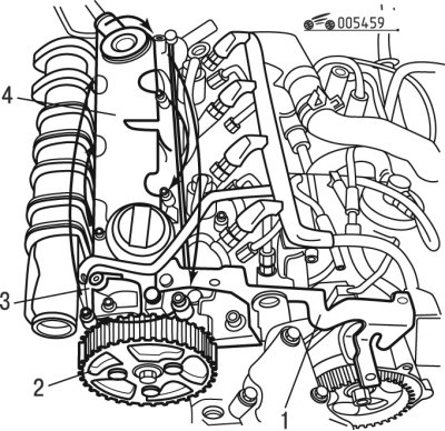
Figure 4.59. Removing the cylinder head cover: 1 - support; 2 - pulley; 3 - connector; 4 - lid
- disconnect connector 3 (figure 4.59);
- remove caliper 1;
- remove the hub with pulley 2;
- remove the cylinder head cover 4;
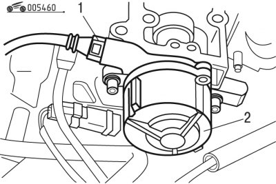
Figure 4.60. Removing the vacuum pump: 1 - hose; 2 - vacuum pump
- move hose 1 to the side (figure 4.60) vacuum brake booster;
- remove vacuum pump 2;
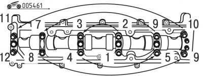
Figure 4.61. Sequence of tightening/loosening the camshaft bearing housing bolts
- loosen the camshaft bearing housing mounting bolts one by one in the order shown in Figure 4.61;
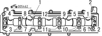
Figure 4.62. Removing the camshaft: 1 - camshaft; 2 - bearing housing
- remove case 2 (figure 4.62) camshaft bearings;
- remove camshaft 1;
- remove the camshaft oil seal;
- clean the camshaft seal seating surfaces using an approved cleaner.
Warning! It is prohibited to use abrasive or piercing-cutting devices and tools.
Install the camshaft in the following order:
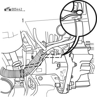
Figure 4.42. Fixing the flywheel: 1 - stopper
- install the stopper (see figure 4.42);
- install the crankshaft pulley mounting bolt;
- remove the stopper from the flywheel;
- turn the crankshaft a quarter turn in the opposite direction (the pistons are in the middle of the working stroke);
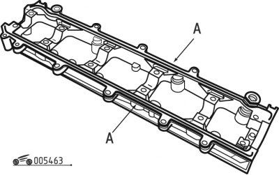
Figure 4.63. Applying sealant to the housing surface: A - surface for applying sealant
- apply SILICONE CATEGORIE 2 sealant (AUTOJOINT OR) around the entire perimeter of A (figure 4.63) surfaces for gaskets;
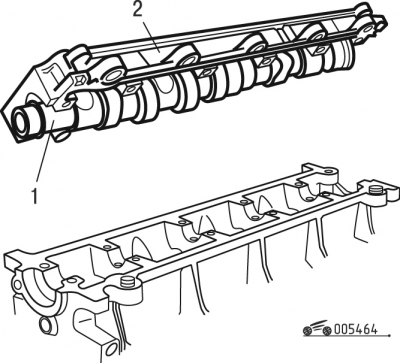
Figure 4.64. Installing the bearing housing: 1 - camshaft; 2 - bearing housing
- install camshaft 1 (figure 4.64) in the housing 2 bearings;
- install the bearing housing with the camshaft on the cylinder head;
- tighten the bearing housing mounting bolts by hand, and then tighten them to a torque of 10 N·m in the sequence shown in Figure 4.61;
- before installing the camshaft oil seal, make sure there is no sealant residue in the seat;
- pack the space between the lips of the seal with grease;
Caution! Do not allow grease to come into contact with the outer surface of the seal.
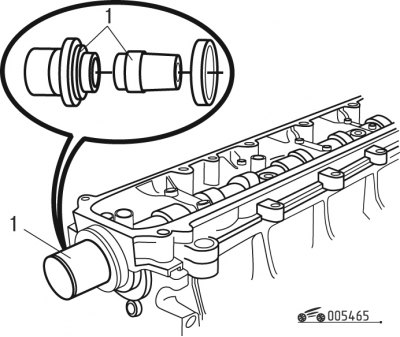
Figure 4.65. Installing the camshaft oil seal: 1 - device
- install a new seal using tool 1 (figure 4.65);
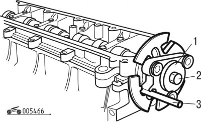
Figure 4.66. Installing the camshaft flange: 1 - flange; 2 - bolt; 3 - device
- install flange 1 (figure 4.66) camshaft;
- screw in bolt 2;
- set the camshaft hub mark using tool 3;
- tighten bolt 2 to 43 Nm;
- lubricate the O-ring seals before installing them;
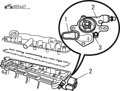
Figure 4.67. Installing the vacuum pump: 1, 3 - sealing rings; 2 - vacuum pump
- install new sealing ring 1 (figure 4.67);
- install a new sealing ring 3;
- install vacuum pump 2;
- tighten the mounting bolts to 20 Nm and the nut to 20 Nm;
- install the head cover with a new gasket;
- tighten the cylinder head cover mounting bolts one by one, in a spiral in the order shown in Figure 4.61, starting with the inner one, to a torque of 10 N·m;
- turn the crankshaft 1/4 turn in the direction of working rotation;
- lock the flywheel with the locking pin 1 (see figure 4.42);
- install the camshaft pulley;
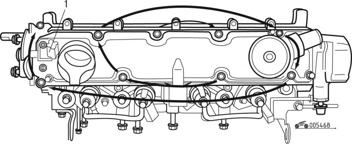
Figure 4.68. Checking the sensor: 1 - sensor
- adjust the gap of sensor 1 (figure 4.68);
- proceed with installation in the reverse order of removal.
DW8 Engine
When removing and installing the camshaft, Peugeot service centers use the following special tool:
- auxiliary key - 0132-AA;
- seal installation tool - 0188-C2;
- mandrel for installing camshaft oil seal - 0188-C1.
Remove the camshaft in the following order:
- disconnect the negative battery cable;
- install the stopper on the flywheel;
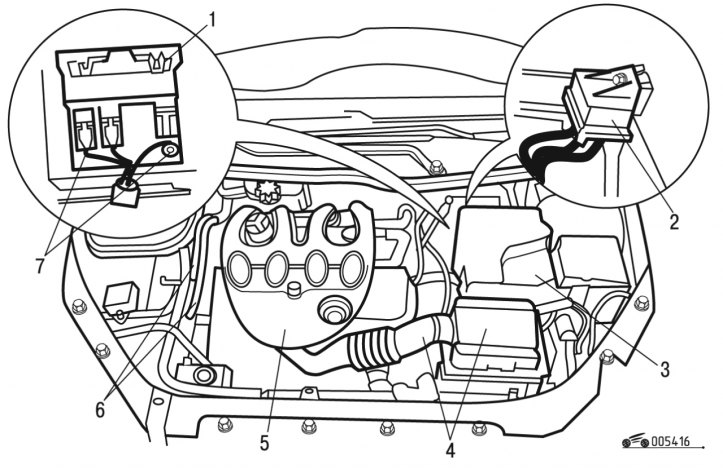
Figure 4.16. Removing the battery: 1 - relay block; 2 - preheating unit; 3 - battery; 4 - air cleaner unit; 5 - decorative cover; 6 - nipples; 7 - bolts
- remove decorative cover 5 (see figure 4.16);
- remove block 4 of the air cleaner with all the wiring;
- remove the air intake distributor;
- remove the exhaust gas recirculation valve tube;
- remove the vacuum pump;
- remove the mounting clamps, disconnect and move aside the contact connectors and wire harnesses passing in the cylinder head area;
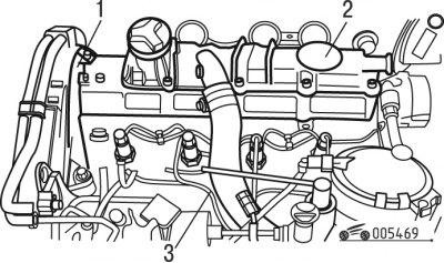
Figure 4.69. Removing the cylinder head covers: 1 - bottom cover; 2 - top cover; 3 - tube
- release the tube 3 (figure 4.69);
- remove the timing belt as described above;
- remove the pulley with the hub on the camshaft using a device;
- remove the top cover 2 of the cylinder head;
- remove the lower cover 1 of the cylinder head;
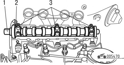
Figure 4.70. Removing the camshaft: 1 - key; 2 - camshaft; 3 - lids
- remove key 1 (figure 4.70);
- gradually, one by one, unscrew the bolts securing the 3 bearing caps;
- remove camshaft 2.
Install the camshaft in the following order:
- remove the tool from the flywheel;
- turn the crankshaft a quarter turn in the opposite direction (the pistons are located in the middle of the working stroke);
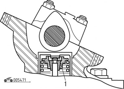
Figure 4.71. Installing adjusting washers in the valve mechanism: 1 - washer
- if replacing the camshaft or tappets, install the base adjusting washers 1 (figure 4.71) 2.425 mm thick;
- lubricate the bearings and cams with engine oil;
- install camshaft 2 (see figure 4.70);
- install 3 bearing caps (the mark is located on the flywheel side of the crankshaft);
- tighten the bearing caps one by one to a torque of 20 Nm;
- check the valve clearances;
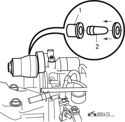
Figure 4.72. Installing the camshaft oil seal: 1, 2 - devices
- place a new seal on the mandrel 1 (figure 4.72) using tool 2;
- install a new seal using tool 1;
- install key 1 (see figure 4.70);
- install the pulley with the hub on the camshaft;
- tighten the mounting bolt to 43 Nm;
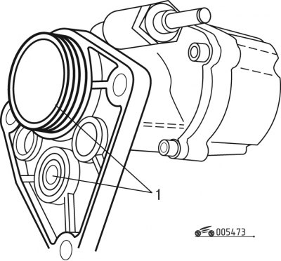
Figure 4.73. Vacuum pump: 1 - sealing cuffs
- install the vacuum pump, lubricating the O-ring seals 1 (figure 4.73) before installation;
- install the bottom cover 1 (see figure 4.69) cylinder heads;
- install the top cover 2 of the cylinder head;
- tighten the mounting bolts to 20 Nm;
- continue installation in the reverse order of removal;
- program all electronic devices in the vehicle.