



- belt tensioner lever stop - 0188-J2;
- dynamic Roller Mounting Pin - 0188-G.
Remove the accessory drive belt in the following order:
- remove the front right wheel;
- move the front right mudguard;
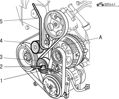
Figure 4.41. Removing the accessory drive belt: 1, 5 - devices; 2 - roller mount; 3, 4 - rollers
- unscrew fastening 2 (figure 4.41), acting on the tension roller 3 using the device 1 until the device 5 enters the calibrated hole A and the generator support;
Note: If the drive belt is missing, apply force to the tensioner with a rod (1/2 inch) until pin 5 is in place.
- remove the accessory drive belt.
Install the accessory drive belt in the following order:
- make sure rollers 3 and 4 rotate freely (without gaps and jams);
- install the belt;
Caution: Make sure the belt is correctly installed on all pulleys and rollers.
- press tension roller 3 with tool 1 in a clockwise direction to release tool 5 in hole A for adjustment;
- without changing this position, tighten fastening 2 to a torque of 50 Nm;
- remove fixture 1;
- turn the engine crankshaft 4 revolutions;
- check the alignment of hole A for adjustment - pin 5 should fit freely into place;
- if necessary, repeat the adjustment;
- proceed with installation in the reverse order of removal.