



Table of contents: Examination 🠇 Manual regulator on the lower…🠇 Manually adjustable sliding tension…🠇 Spring loaded tension pulley with…🠇
Note: Peugeot/Citroen requires the use of a special electronic tool (sEEM C.TRONIC belt tension measuring tool, type 105) for correct adjustment of the tension of the auxiliary drive belt equipped with a manually adjustable tensioner. This procedure varies greatly depending on engine type, model year, and belt type and condition. The procedure described below is an alternative method that does not require the use of electronic equipment. If any problems arise (for example, squealing when starting) the tension should be checked by a dealer using a special electronic tool at the earliest opportunity.
1. Depending on the specification, the vehicle is equipped with one or two accessory drive belts. If two belts are installed, replacing the inner belt will require removing the outer belt.
Examination
2. Place wheel chocks under the rear wheels. Raise the front of the vehicle and support it securely (see "Lifting and installing the car on supports"). Remove the right front wheel.
3. From under the front of the vehicle, remove the screws, remove the clips and remove the wheel arch liner to gain access to the crankshaft sprocket/pulley bolt. If necessary, release the coolant hoses from the clips on the fender for easier access later.
4. Using a suitable socket and extension, slowly rotate the crankshaft by the crankshaft sprocket/pulley bolt while inspecting the drive belt along its entire length. Inspect the drive belt(s) for cracks, cuts, abrasions, or other damage. Also check the belt for signs of "glazing," which makes the belt shiny, and signs of delamination. If the belt is worn or damaged, replace it.
5. If the belt condition is satisfactory, on models where the belt is adjusted manually, check its tension as described below, taking into account the note given at the beginning of this paragraph. On models with an automatic spring-loaded tensioner, there is no need to check the drive belt tension.
Manual regulator on the lower support of the generator
Removal
6. Follow the steps described in paragraph. points 2 and 3, if you haven't done so yet.
7. Disconnect the ground cable from the battery (see "Disconnecting the battery" in the Appendix).
8. Loosen the upper and lower generator mounting bolts and, if applicable, the adjuster bar mounting bolt (figure 10.8, a, b).
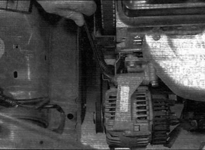
Figure 10.8,a. Loosen the upper generator mounting bolt...
9. If necessary, turn the adjusting bolt to relieve tension on the drive belt, then remove the belt from the pulleys (figure 10.9, a, 6).
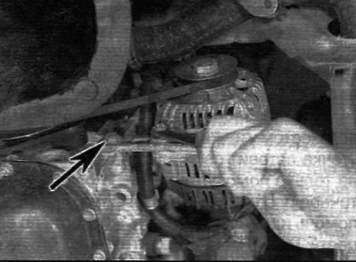
Figure 10.8, b....lower bolt and adjusting bar (marked with an arrow) (models with a manual regulator on the lower generator support)
Note: If the belt is to be reused, mark the direction of rotation on it before removing it. This will ensure that the belt is installed correctly.
Installation
10. When replacing a belt, ensure that the new belt is the correct type, and if installing a removed belt, follow the marks made during removal to ensure it is installed correctly. Place the belt on the pulleys and use the adjusting bolt to take up the belt slack.
11. Tighten the drive belt as described in the following paragraphs.
Stretching
12. Follow the steps described in paragraph. points 2 and 3, if you haven't done so yet.
13. The belt should be tensioned so that when pressing firmly with your thumb in the middle of the longest section between the pulleys there is a deflection of approximately 5.0 mm (see the note at the beginning of this paragraph).
Advice: Proper drive belt tension ensures reliable operation throughout its entire service life, while slack causes slippage and squealing. Be careful not to exceed the required tension as this may cause increased wear on the generator bearings.
14. To make adjustments, turn the adjusting bolt to achieve the correct tension. This should be done in a position where the mounting bolts hold the generator but still allow for slight movement.
15. Rotate the crankshaft two revolutions, check the tension again, and then tighten both generator mounts. If applicable, also tighten the bolt securing the adjuster bar to the corresponding support bracket.
16. Connect the ground wire to the battery.
17. Secure the coolant hoses in their normal position (where necessary) and install the wheel arch liner. Install the wheel and lower the vehicle.
Manually adjustable sliding tension pulley
Removal
18. Perform the actions according to item. points 2 and 3, if you haven't done so yet.
19. Disconnect the ground cable from the battery (refer to paragraph "Disconnecting the battery").
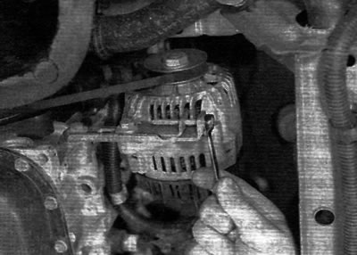
Figure 10.9, a. Turn the adjusting bolt to relieve tension on the drive belt...
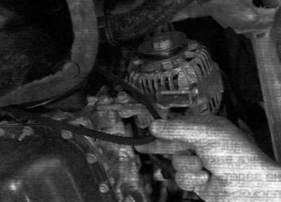
Figure 10.9, b....then remove the belt from the pulleys (models with a manual regulator on the lower generator support)
20. Loosen the two bolts securing the tension pulley assembly to the engine (figure 10.20).
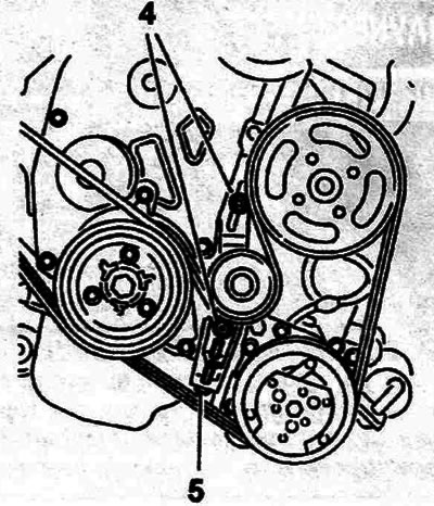
Figure 10.20. Tension pulley mounting screws (4) and adjusting bolt (5) (models with a manually adjustable sliding tension pulley)
21. Turn the tensioner bolt to move the tensioner pulley away from the drive belt until there is enough slack in the drive belt to remove the belt from the pulleys. Note: If the belt is to be used again, mark the direction of rotation on the belt before removing it. This will ensure that the belt is installed correctly.
Installation
22. When replacing a belt, ensure that the new belt is the correct type, and if installing a removed belt, follow the marks made during removal to ensure it is installed correctly. Place the belt on the pulleys so that the belt ribs fit correctly into the grooves on the pulleys and the belt is routed properly. Use the tensioner pulley adjusting bolt to remove any slack from the belt. Tighten the belt as described below.
Stretching
23. Perform the actions according to item. points 2 and 3, if you haven't done so yet.
24. Correct tension of the drive belt ensures its long service life.
25. The belt should be tensioned so that when pressing firmly with the thumb, the deflection at the middle of the longest section between the pulleys is approximately 5.0 mm (see the note at the beginning of this paragraph).
26. To adjust the tension, loosen the two tension pulley assembly mounting bolts and turn the adjusting bolt until the correct tension is achieved. Once the belt is tensioned correctly, rotate the crankshaft two revolutions and check the tension again.
27. After ensuring that the belt tension is correct, securely tighten the tension pulley assembly mounting bolts, and then connect the ground wire to the battery.
28. Secure the coolant hoses and install the wheel arch liner. Install the wheel and lower the vehicle. Fixed tensioner pulley with manual adjustment.
Removal
29. Perform the actions according to item. points 2 and 3, if you haven't done so yet.
30. Disconnect the ground cable from the battery (refer to paragraph "Disconnecting the battery").
31. Loosen the tensioner pulley retaining nut and turn the center bolt to move the pulley away from the drive belt until there is enough slack in the drive belt to remove the belt from the pulleys (figure 10.31). Note: If the belt is to be used again, mark the direction of rotation on the belt before removing it. This will ensure that the belt is installed correctly.
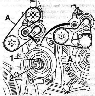
Figure 10.31. Loosen the pulley nut (1) and turn the center bolt (2) to adjust the drive belt tension. The callout shows the belt tension check point (A) (models with a fixed tension pulley with manual adjustment)
Installation
32. When replacing a belt, ensure that the new belt is the correct type, and if installing a removed belt, follow the marks made during removal to ensure it is installed correctly. Place the belt on the pulleys so that the belt ribs fit correctly into the grooves on the pulleys and the belt is routed properly. Tighten the belt as described below.
Stretching
33. Perform the actions according to item. points 2 and 3, if you haven't done so yet.
34. Correct drive belt tension will ensure long belt life (see "Haynes Advises" above).
35. The belt should be tensioned so that when pressed firmly with the thumb, the deflection at the middle of the longest section between the pulleys is approximately 5.0 mm (see the note at the beginning of this paragraph).
36. To adjust the tension, loosen the tension pulley mounting nut and turn the center bolt until the correct tension is achieved. Once the belt is properly tensioned, hold the center bolt and tighten the pulley retaining nut securely. Turn the crankshaft two revolutions and check the tension again.
37. Secure the coolant hoses and install the wheel arch liner. Install the wheel and lower the vehicle.
Spring loaded tension pulley with automatic adjustment
Removal
38. Perform the actions according to item. points 2 and 3, if you haven't done so yet.
39. Disconnect the ground cable from the battery (refer to paragraph "Disconnecting the battery").
40. If necessary, remove the screws from the power steering pump pulley shield and remove the shield to gain access to the top of the drive belt.
41. Move the pulley away from the drive belt using a wrench on the pulley mounting nut. Turn the tension pulley counterclockwise to move it away from the belt. Note: The tensioner pulley has a left-hand thread and therefore will not release when the belt tension is released.
42. After releasing the tension, to hold the pulley in the released position, insert a 4.0 mm Allen key into the hole at the base of the pulley assembly. Remove the belt from all pulleys, first marking the belt routing, and remove the belt from the engine. Note: If the belt is to be used again, mark the direction of rotation on the belt before removing it. This will ensure that the belt is installed correctly.
Installation and tensioning
43. When replacing a belt, ensure that the new belt is the correct type, and if installing a removed belt, follow the marks made during removal to ensure it is installed correctly. Place the belt on the pulleys so that the belt ribs fit correctly into the grooves on the pulleys and the belt is routed properly.
44. Remove the load from the tension pulley and remove the internal Allen key. Release the pulley and allow the tensioner to automatically tighten the belt.
45. Install the power steering pump pulley shield (if removed) and securely tighten the associated screws.
46. Connect the ground wire to the battery.
47. Secure the coolant hoses and install the wheel arch liner. Install the wheel and lower the vehicle.