
English Русский
Български
Беларускі
Український
Српски
Hrvatski
Română
Polski
Slovenský
Magyar
Bookmark Articles Sitemap Contacts
Company Hyundai Company Opel Company Skoda Company Kia Company Mitsubishi Company LADA Company Audi
PeugeotBook.ru


Series 100   Series 200   Series 300   400-500   Series 600   Crossovers   Others
 
Peugeot 405 (1987-1997) Peugeot 406 (1995-2004)

Disassembling a diesel engine (Peugeot 405)

  • Main
  • 40X
  • Peugeot 405 (1987-1997)
  • Power unit
  • Diesel engines
  • Disassembling a diesel engine
0

Engine block, oil pan and timing case
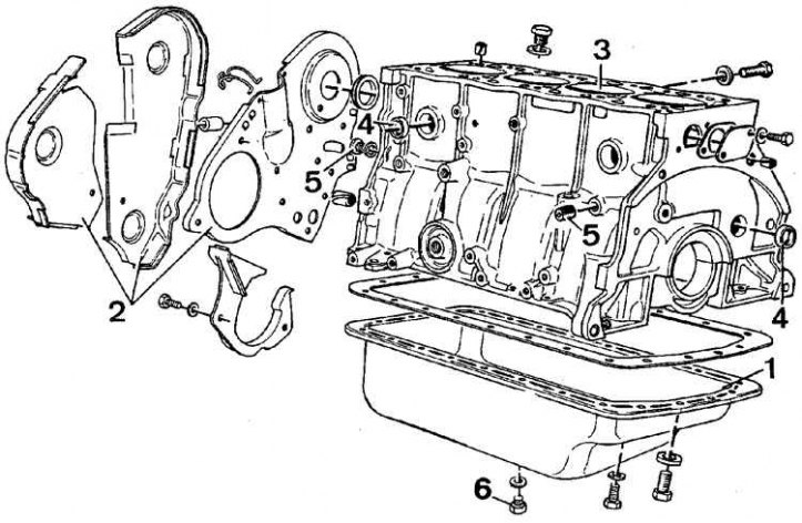


1 – oil pan, 2 – timing drive housings, 3 – engine cylinder block, 4, 5 – plugs, 6 – oil drain plug

1 – oil pan, 2 – timing drive housings, 3 – engine cylinder block, 4, 5 – plugs, 6 – oil drain plug


Crank mechanism
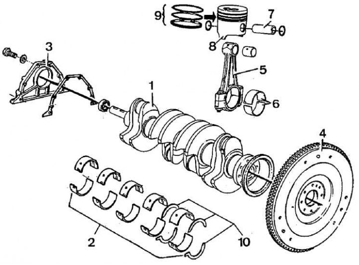


1 – crankshaft, 2 – bearing shells, 3 – front bearing cap, 4 – flywheel, 5 – connecting rod, 6 –…

1 – crankshaft, 2 – bearing shells, 3 – front bearing cap, 4 – flywheel, 5 – connecting rod, 6 – shells, 7 – piston pin, 8 – piston, 9 – piston rings, 10 – thrust half rings for adjusting the axial play of the crankshaft


1. Remove the oil vapor drain pipes and the coolant hose.

2. Remove the receiver and lift bracket in the XUD 9 engine.

3. Remove the generator and belt.

4. Remove the pulley attached to the end of the camshaft, the pump and the belt.

5. For XUD 7TE engines, remove the intake manifold, turbocharger and exhaust manifold.

6. Remove the drive housing and the support element located on the central bolt.


7. Remove the crankshaft pulley and lower plastic cover.

8. Remove the glow plugs.

9. Turn the engine crankshaft to a position that allows the elements of the valve timing system to be locked: the holes in the crankshaft and fuel filter pulleys must be in a position that corresponds to the position of the threaded holes made behind the pulleys.

10. Insert the locking bolts 7.0153 G and tighten them by hand (see figure Method of fixing elements of the camshaft drive):
  • screw one long bolt into the camshaft pulley;
  • screw two short bolts into the fuel pump pulley.

11. Unscrew the camshaft pulley mounting bolt and the central fuel pump mounting nut.

12. Release the drive belt tension roller by unscrewing the nut (1, see figure Adjusting the Timing Belt Tensioner Roller) axle bolt and bolt (2):
  • press the tension roller at (3) using a 9.53 mm square wrench (3/8 inch junior Fac) to compress the spring.

13. Screw in the bolt and nut.

14. Remove the toothed belt. Do not bend the toothed belt. It should not have contact with oil, water, coolant or grease.

15. Remove the high pressure fuel pump and pump pulley.

16. Remove the camshaft and crankshaft pulleys.

17. Remove the coolant pump and seal (5 bolts).

18. Remove the upper bolt and nut of the tension roller axle.

19. Remove the tension roller, push rod and spring.

20. Remove the engine bracket and roller.

21. Remove the fuel pump bracket and the two bracket mounting guide pins from the engine block.

22. Remove the cylinder head cover and engine block.

23. Unscrew the bolt and remove the support element near the manifold.


24. Remove the cylinder head cover.

25. Unscrew the camshaft bearing caps one by one and remove the camshaft. The bearing caps are marked 1 through 3 (No. 1 on the flywheel side).

26. Loosen the cylinder head mounting bolts in a spiral pattern, starting from the outside (reverse order of screwing).

27. Remove the bolts and washers.

28. Use a lever to tilt the engine forward to remove the pin.

29. Remove the cylinder head and gasket.

30. Remove the flywheel.

31. Turn the engine over.

32. Remove the oil pan.

33. Remove the timing drive side seal cover and remove the paper gasket.

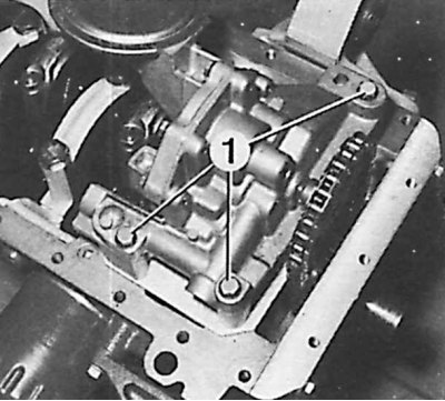
34. Remove the three oil pump mounting bolts.

35. Remove the chain and sprocket with key secured to the end of the crankshaft.

36. Remove the connecting rod caps, mark their order and method of attachment.
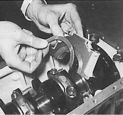
36. Remove the connecting rod caps, mark their order and method of attachment.


37. Remove the main bearing caps and liners, as well as the thrust washers.

(Original is located at: www.PEUGEOTBOOK.ru)

38. Remove the crankshaft.

39. Remove the connecting rod-piston assemblies.

40. Remove the grooved bearings installed in the engine cylinder block.
40. Remove the grooved bearings installed in the engine cylinder block.


41. Unscrew the oil channel plugs (1) and the oil pressure sensor. Clean the oil channels. Install the plugs and sensor.


42. In the connecting rod-piston kit, remove the pin retaining spring ring and remove the pin.

43. In XUD 7TE engines, remove the piston cooling oil supply nozzle.

44. Clean all oil passages thoroughly.
This article is available at russian, bulgarian, belarusian, ukrainian, serbian, croatian, romanian, polish, slovak, hungarian
Article reviewed by editor: Shirokov Arseny
Share information:
Previous
Peugeot 405: Diesel engines
Next

Installation of a diesel engine
Removal a diesel engine
Cylinder head repair
Installing the cylinder head
Removal the cylinder head
Assembly of a diesel engine
Oil pump — removal and installation
See similar information for other Peugeot models

➨ Diesel engine in-car repair procedures — specifications Peugeot 106 (1991-2003)
➨ Cooling system device (diesel engine) Peugeot 207 (2006-2014)
➨ Disassembling the XU series engine Peugeot 305 (1977-1989)
➨ Engine compartment. Cars with a 2.5 liter diesel engine Peugeot 605 (1989-2000)
➨ Diesel engine — disassembly and assembly Peugeot 806 (1994-2002)
Link to this article in different formats
Comments and feedback from visitors
No comments yet


Add two numbers 37 + 47


Peugeot 406 (1995-2004) 
  • General information
  • User manual
  • Maintenance (gasoline)
  • Maintenance (diesel)
  • Power unit
  • Gasoline engines
  • Diesel engines
  • Engine overhaul
  • Cooling and heating
  • Fuel system (gasoline)
  • Fuel system (diesel)
  • Engine electrical equipment
  • Transmission
  • Clutch and drive shafts
  • Mechanical gearbox
  • Automatic gearbox
  • Chassis, running gear
  • Brake system
  • Car suspension
  • Steering
  • Body and interior
  • Exterior (external elements)
  • Interior (internal elements)
  • Doors, locks and windows
  • Electrical equipment
  • Equipment and devices
  • Electrical circuits
Peugeot 405 (1987-1997) 
  • General information
  • User manual
  • Maintenance
  • Power unit
  • Petrol engines 1.4 l
  • Petrol engines 1.6-2.0 l
  • Diesel engines
  • Ignition system
  • Fuel system (carburetor)
  • Single point fuel injection
  • Multipoint fuel injection
  • Cooling and lubrication system
  • Exhaust system
  • Transmission
  • Clutch
  • Manual gearbox MA
  • Manual gearbox BE
  • Automatic gearbox
  • Drive shafts
  • Chassis, running gear
  • Steering
  • Front suspension
  • Rear suspension
  • Brake system
  • Body and interior
  • Exterior (external elements)
  • Interior (internal elements)
  • Doors, locks and windows
  • Electrical equipment
  • Equipment and devices
  • Electrical circuits
PeugeotBook.ru © 2018–2026 | Mobile version | Sitemap: EN BG BY UA RS HR RO PL SK HU | Write message | Site search | Add to bookmarks | Peugeot owners
106 (1991-2003) | 206 (1998-2012) | 207 (2006-2014) | 305 (1977-1989) | 306 (1993-2002) | 307 (2001-2008) | 405 (1987-1997) | 406 (1995-2004) | 605 (1989-2000) | Partner-I (1996-2008) | Eurovans-807 (2002-2014) | Eurovans-806 (1994-2002) | J5 (1981-1993) |
Cookies are used to ensure the correct display of pages on the site.