
Head Gasket Identification
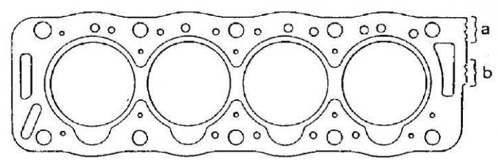
a - without cutout: XUD 9 engine; with cutout: motor XUD 7TE, b - thickness designation
The position of the guide pin installation of the cylinder head
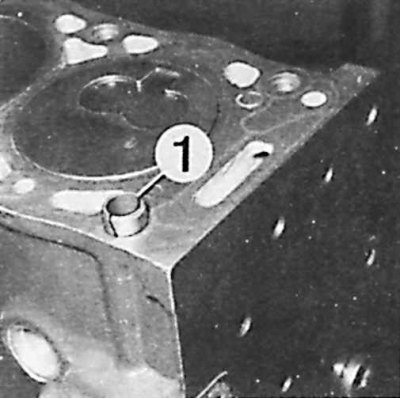
1 – a guide pin of installation of a head of the block of cylinders
Cylinder head bolt tightening sequence and valve placement
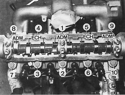
ADM - intake valve cam,
ECH - exhaust valve cam
1. Clean the connection surface with "Decaploc 82". Do not use abrasive products or sharp instruments.
2. Make sure the connection surface is free of scratches and impact marks.
3. Check the flatness of the connecting surface of the cylinder head to the cylinder block. If necessary, this surface can be re-sanded.
4. Using a dial gauge, measure the protrusion of the pistons above the surface of the cylinder block.
5. Using a dial gauge, measure the center setting of each piston. The maximum allowable difference between the two pistons is 0.12 mm. The largest value measured determines the thickness of the cylinder head gasket that should be used. Cylinder head gaskets are marked with special cutouts.
6. Select the thickness of the cylinder head gasket.
7. Check if the camshaft is in the locked position so that the valves of the block of cylinders No. 1 and No. 4 are fully closed (install the camshaft sprocket and screw in the locking screw).
8. Degrease (remove all traces of grease) and drain the cylinder head bolt holes.
9. The engine must be blocked. Using a M12x150 tap, clean the threads in the holes in the engine block and clean them with a jet of air.
10. Install the guide pin on the engine block joint surface.
11. Install the cylinder head gasket (only one position).
12. Install the cylinder head.
13. Lubricate the cylinder head bolts (under the heads and on the thread) means "Molykote G Rapid", insert new gaskets with the convex side up. Install the cylinder head bolts.
14. Install the cylinder head bolts following the instructions below:
- screw first according to the sequence (see fig. Cylinder head bolt tightening sequence and valve placement) torque 30 Nm;
- screw in according to the sequence with a torque of 70 Nm;
- tighten in accordance with the sequence by an angle of 120°.
15. If necessary, adjust the valve clearance and replace the camshaft O-ring.
16. Screw in the bolts (2) And (3) tension roller and engine bracket.
17. At the end of the camshaft, install the toothed pulley with the key and screw in the blocking bolt (it must be screwed by hand).
18. Tighten the toothed pulley mounting bolt to a torque of 35–40 Nm.
19. Install the camshaft timing belt.
20. Install the left engine lift bracket.
21. Connect the exhaust pipe.
22. On the XUD 7TE engine, install the intake manifold and right holder.
23. Connect coolant hoses, fuel, electrical connections. Connect the high speed idle rod to the pump.
24. Install the power steering pump belt (depending on equipment) and pull it up.
25. Turn the engine crankshaft and, if necessary, replenish the amount of coolant to the required level.
26. Adjust idling with increased RPM.
| Piston protrusion (mm) | Designation (b) (see fig. Head Gasket Identification) |
| 0,54 – 0,77 | 2 cutouts |
| 0,77 – 0,82 | 3 cutouts |