
Placement of the oil channel plug between the filter and the main channel
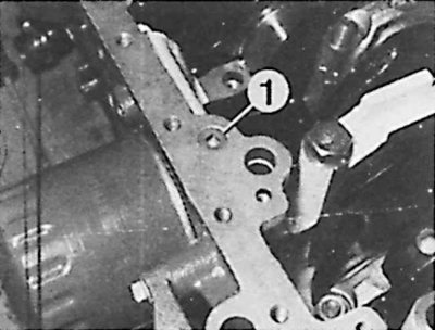
1 - channel between the filter and the main channel
Placement of plugs of the main oil channels
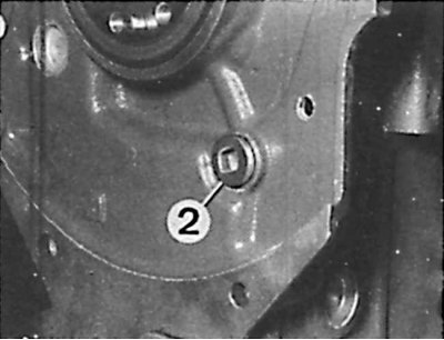
2, 3 - main channels | 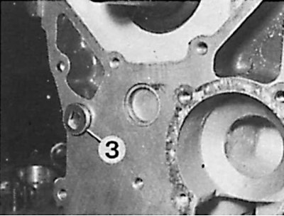 |
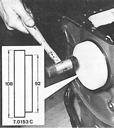
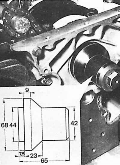
Installing the sealing ring on the flywheel side of the engine
Application sites "Rectijoint" for sealing the #1 crankshaft main bearing on later engine models
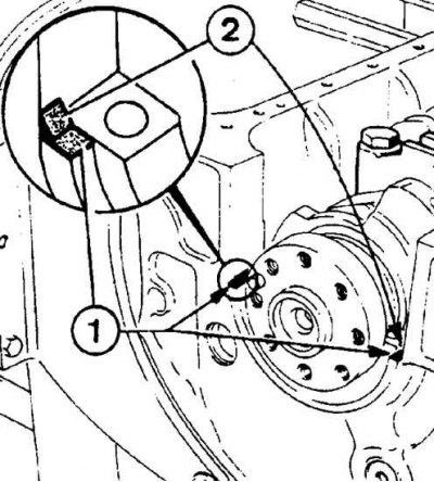
1, 2 - places of application of the agent "Rectijoint"
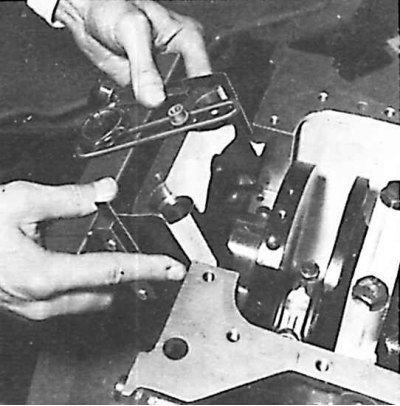
Installing the o-ring in the front bearing housing
1. All o-rings, seals and gaskets should be replaced.
2. Lubricate rubbing surfaces with engine oil.
3. Observe the factory designations and marks made during disassembly.
4. On XUD 7TE engines, install an oil jet to cool the pistons.
5. Install grooved liners in the engine block, and smooth liners in the main bearing caps.
6. Install the crankshaft and main bearing caps #3, 4, and 5.
7. Install the thrust washers with the copper plated surface away from the crankshaft, and then install the #2 main bearing cap.
8. Clean the joint surface of the engine block and bearing cap No. 1, removing all traces of grease from them.
9. Apply a small amount of sealant to the engine block at the top of the #1 bearing grooves "Loctite Frenetanch".
10. Install the bearing cover on the adjusted fixture 7.0153 A1, equipped with additional elements A2 (0.15 mm thick) and use the bolt to secure the cover to the clasp of the tool.
11. Lubricate the additional elements and fix the bearing cover in such a way that the side seals are not deformed:
- place the device-lid assembly inclined at 45°in the socket;
- straighten the knot;
- lower slowly;
- secure the cover with one bolt;
- remove the tool in a horizontal plane.
12. Tighten the bearing cap bolts to 70 Nm.
13. On later models, to prevent oil leakage in the area of the main bearing of the crankshaft, a sealing agent called "Rectijoint". Means "Rectijoint" should be applied to the ends (1, see fig. Application sites "Rectijoint" for sealing the #1 crankshaft main bearing on later engine models) #1 main bearing as previously given and in the flexures of that bearing.
14. Check if the crankshaft rotates freely.
15. Install a dial indicator on the engine block on the timing side: tools 8.0110 GY and 0.0117.2 should be used.
16. Check the end play of the crankshaft, which should be 0.07–0.32 mm.
17. On the flywheel side, install the O-ring using special tool 7.0153 C. Before this, oil the working surface, socket and ring.
18. Locate the locks on the piston rings evenly around the perimeter of the piston and secure the connecting rod-piston assemblies. The characteristic recesses in the bottoms of the pistons should be directed towards the fuel pump. The connecting rod lugs are installed on the same side.
19. Tighten the connecting rod cap nuts to 50 Nm.
20. Check the torque of the crank mechanism. A torque wrench must be used, attached to the tip 8.0110 EZ, mounted on the crankshaft in place of the flywheel. The measured torque must not exceed 40 Nm.
21. Align the ends of the side seals of the bearing cap #1 by 1 mm with the connection surface (use a stylus blade).
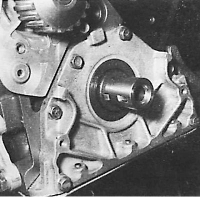
22. Install the oil pump drive sprocket with the key and chain, install the seal and cover.
23. Install the O-ring with oiled lips in the seat (also lubricated with oil) in the lid.
24. Install the chain on the oil pump sprocket.
25. Install the pump on the engine block and secure it.
26. Apply a small amount of sealing paste "Peugeot" on the engine block-cover connection and on the connection surface.
27. Install the oil pan gasket, oil pan and tighten the mounting bolts (the three bolts on the cover are pan head bolts with a hex socket).
28. Install the gear by screwing the coated "Loctite Frenetanch" bolts with a torque of 50 Nm.
29. Check piston protrusion and valve chamfer.
30. Install tappets and shims or main shims 2.425 mm thick in the cylinder head.
31. Using a M12x150 tap, clean the threads in the holes in the engine block.
32. Rotate the crankshaft so that the pistons are in the middle of the stroke; the pulley keyway should point to nine o'clock.
33. Install the cylinder head gasket and head; bolt projections must be dry and free from grease.
34. Insert clean bolts. These bolts under the heads and on the threads must be coated with "Molykote Rapid". New gaskets must be installed with the convex side up.
35. Tighten the bolts in the order shown in fig. Cylinder head bolt tightening sequence and valve placement.
36. Check and adjust valve clearance.
37. After selecting eight adjusting plates, place them in the appropriate place and insert the pushers.
38. After applying to the working surfaces of the camshaft means " Molykoteg Rapid" install the camshaft in the head. The placement of the camshaft determines the sign "DIST", which must be located on the side of the gas distribution drive.
39. Clean the connecting surfaces of the cylinder head and bearing caps, remove all traces of grease from them.
40. Apply a product to the ends of the cylinder head "Loctite", protecting threaded connections from spontaneous unscrewing.
41. Install bearing caps (#1 flywheel side) and gradually tighten them to a torque of 15–17.5 Nm.
42. Using tool 7.0153E and the pulley mounting bolt, install new camshaft sealing rings.
43. Install the fuel pump holder.
44. Establish a casing of a head of the block of cylinders and the block of cylinders of the engine.
45. Install the water pump with seal. Bolts should be tightened to 10 Nm.
46. Install the fuel pump and gas distribution system.
47. On XUD 7TE engines, install the intake manifold.