
Place of measuring the height of the cylinder head and the sign of the reground head
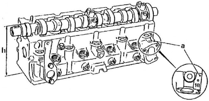
h is the height of the cylinder head,
a - the location of the sign of the polished head,
R - sign of a reground head
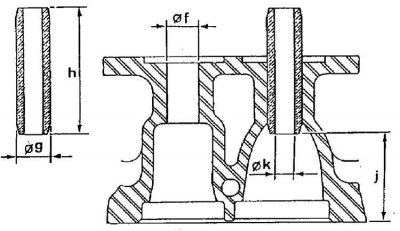
Valve guide dimensions
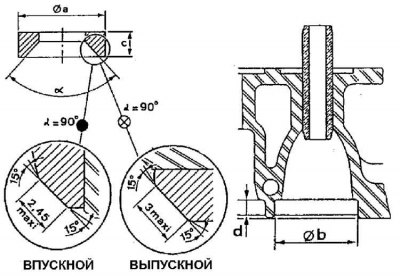
Valve seat dimensions
Comparison of valve seats on early and late models
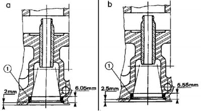
a - the old type,
b - new type,
1 - valve seats
1. Remove the cylinder head.
2. Gradually loosen the camshaft bearing caps.
3. Remove the bearing caps, marking the direction of their attachment.
4. Remove the O-ring located at the end of the camshaft.
5. Remove the camshaft.
6. Designate and remove pushers of valves.
7. Using a special clip, remove the valves together with their springs and arrange them in order.
8. Remove swirl chambers by knocking them out through the nozzle hole.
9. Clean the cylinder head. Use a special cleaning agent to clean the connection surface "Decaploc 88".
10. Check the flatness of the connection surface with the engine block (maximum flatness 0.07 mm).
11. If necessary, regrind the cylinder head. To do this, follow these steps:
- regrind the valve seats so as to obtain the required stroke;
- replace swirl chambers with swirl chambers of repair dimensions and achieve the required protrusion value;
- under the valve springs, install compensating gaskets with a thickness of 0.4 mm.
12. Check the condition of the valve guides. If necessary, they should be replaced. This operation should be performed by a qualified technician. Replacing valve guides requires mandatory regrinding or replacement of the corresponding valve seats.
13. Check the condition of the valve seats. If necessary, they should be reground or replaced. This operation should be performed by a qualified technician.
14. Check the condition of the springs and camshaft.
15. Check the protrusion of the swirl chambers (0–0.03 mm).
16. If necessary, achieve the required size by surface treatment "X" And "at" vortex chambers (see fig. Comparison of valve seats on early and late models).
17. Check valve facets.
18. If necessary, achieve the required dimensions by grinding the valve seats.
19. Lap the valves.
20. Install valves.
Attention! If the cylinder head has been ground, then 0.4 mm thick compensating gaskets should be installed under the valve springs.
21. Install 2.425 mm thick plates on the valve stems and check that the plates exceed the spring plates.
22. If the plates do not exceed the plates of the springs, then the upper surfaces of the plates should be ground.
23. Install pushers.
24. Lubricate the camshaft bearings with oil.
25. Install the camshaft "DIST" to the gas distribution drive.
26. Install the bearing caps and gradually tighten them to a torque of 17.5 Nm.
27. Install the cylinder head.