



Table of contents: TU3JP engine 🠇 Engine TU5JP4 🠇
TU3JP engine
Removal
Turn off the ignition and disconnect the ground wire from the battery.
Drain the coolant from the engine cooling system.
Remove the wiper blades.
Remove the plastic windshield deflector.
Remove the plastic windshield crossbar.
Remove the accessory drive belt.
Air filter and air intake pipe.
Remove the decorative battery cover.
Remove the left front wheel arch mudguard.
From under the left front wheel arch, unscrew the battery support mounting bolt.
Remove the battery.
Remove the battery support.
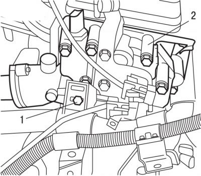
Figure 3.9. Location of the bolt (1) securing the wiring harness to the coolant outlet block (2)
Remove bolt 1 (see figure 3.9) harness support brackets and move the harness away from the coolant outlet block.
Disconnect the wire harnesses going to the coolant outlet block.
Remove the bolts and coolant outlet block.
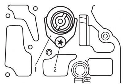
Figure 3.25. Location of bolt (2) for fastening plate (1) for axial fixation of camshaft
Remove bolt 2 (figure 3.25) and remove the axial fixing plate 1 of the camshaft.
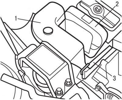
Figure 3.26. Location of the right support (1), toothed belt cover (2) and support corner reinforcement (3)
Remove the right support 1 (figure 3.26) engine and corner amplifier 3 supports.
Remove the timing belt cover 2.
Remove the timing belt.
Caution: Protect the lower stop of the front part of the windshield with a piece of door seal.
Support the engine with a lifting mechanism with clamps.
Using a special device, secure the camshaft pulley from turning and unscrew the pulley mounting bolt.
Unscrew the nuts and remove the cylinder head cover.
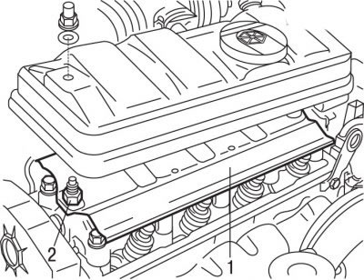
Figure 3.11. Location of spacer (1) and deflector (2) under the cylinder head cover
Remove spacers 1 (see Figure 3.11) and deflector 2.
Rotate the engine crankshaft in the direction of engine rotation to set the piston of cylinder 1 to TDC. To do this, use a special tool to secure the flywheel from turning and then remove the tool.
Turn the engine crankshaft 1/4 turn in the opposite direction.
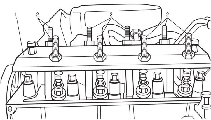
Figure 3.27. Location of the support plate (1) of the rocker arms and bolts (2) for moving the cams away from the camshaft
Install the rocker arm support plate 1 onto the cylinder head (figure 3.27), observing the correct installation direction in relation to the timing drive.
Tighten bolts 2 until all cams move away from the camshaft.
Caution! Tighten bolts 2 just enough to release the cams, but do not allow the valves to contact the pistons.
Remove the camshaft seal ring.
Remove the camshaft.
Installation
Apply a thin layer of MOLYDAL GB SP 370G grease to the bearing journals and camshaft cams.
Install the camshaft into the cylinder head.
Install the axial fixation plates 1 (see Figure 3.25) camshaft and secure it with bolt 2, tightening it to a torque of 15 Nm.
Using a tubular mandrel of the appropriate diameter, install the camshaft seal ring.
Further installation is carried out in the reverse order of removal, taking into account the following.
Clean the mating surfaces of the cylinder head and coolant outlet block.
Lubricate the mating surface of the cylinder head with the coolant outlet block with silicone paste.
You can find the original on the page peugeotbook.ru
Install the timing belt.
Install the accessory drive belt.
Fill the engine cooling system with coolant.
Engine TU5JP4
Removal
Turn off the ignition and disconnect the ground wire from the battery.
Remove the protective cover from the right side of the engine compartment.
Remove the accessory drive belt.
Remove the pulley from the crankshaft.
Support the power unit by placing a support stand under the engine.
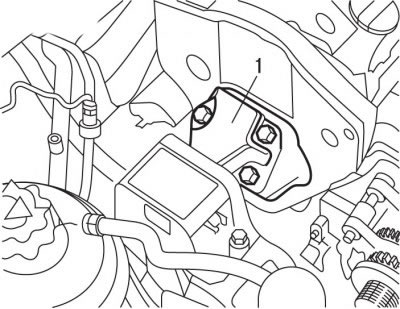
Figure 3.15. Location of the right engine support (1)
Remove the right support 1 (see Figure 3.15) engine assembly.
Remove the upper and lower timing belt covers.
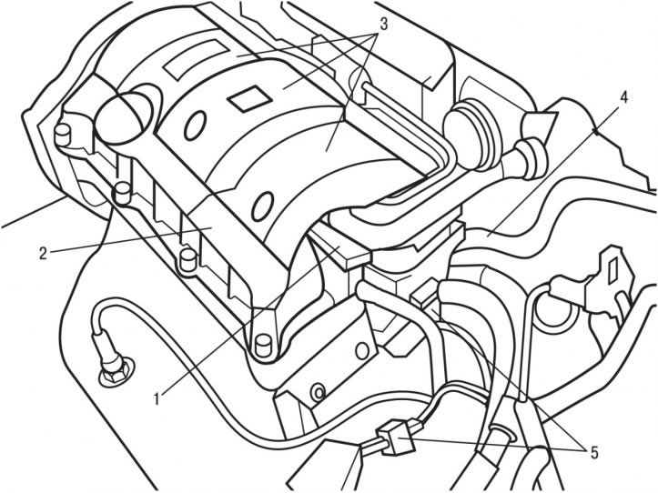
Figure 3.17. Location of the compact ignition coil block: 1 - compact ignition coil block; 2 - lid; cylinder heads; 3 - decorative cover; 4 - air conditioning system heat exchanger tubes; 5-pin connectors
Remove cover 2 (see Figure 3.17) cylinder heads.
Rotate the engine crankshaft in the direction of engine rotation to set the piston of cylinder 1 to TDC. To do this, use a special tool to secure the flywheel from turning and then remove the tool.
Turn the engine crankshaft 1/4 turn in the opposite direction.
In a spiral, starting with the outer bolt, unscrew the bolts securing each cylinder head cover.
Remove the cylinder head covers.
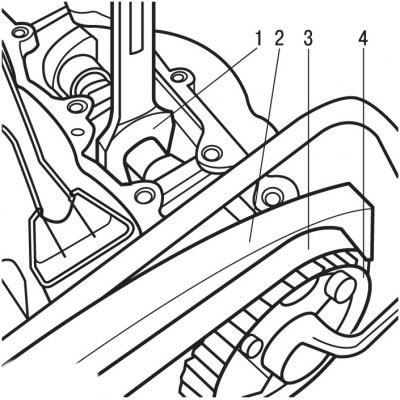
Figure 3.28. Unscrewing the camshaft timing belt pulley hub mounting bolt: 1 - a wrench installed on the flats of the camshaft; 2 - rear toothed belt cover; 3 - toothed belt; 4 - toothed belt pulley
Secured with one wrench 1 (figure 3.28) to prevent the camshaft from turning by the flats, use the second key to unscrew the timing belt pulley hub mounting bolt.
Remove toothed belt 3.
Remove the 4 toothed belt pulley with the hub from the camshaft.
Remove the rear cover 2 of the toothed belt.
Remove the camshaft sealing rings.
Gradually, in a spiral motion, starting with the outer bolt, loosen and then unscrew the camshaft bearing housing bolts until there is a gap of a few millimetres between the mating surfaces.
Remove the camshafts from the liners by tapping them with a wooden hammer from the pulley side.
Completely unscrew the bolts and remove the camshaft bearing housings.
Remove the camshafts.
If you are going to remove the tappets, first mark their location for subsequent installation in their places.
Using a valve lapping type vacuum suction tool, remove the lifters from the cylinder head.
Pump out the oil from the threaded holes for mounting the camshaft bearing housings.
Installation
Install the tappets in place, having previously lubricated them with MOLYDAL GB SP 370G oil.
Make sure the tappets in the cylinder head rotate freely.
Apply a thin layer of MOLYDAL GB SP 370G grease to the bearing journals and camshaft cams.
Install the camshafts into the cylinder head by turning the intake valve shaft alignment groove to the 7 o'clock position and the exhaust valve shaft alignment groove to the 8 o'clock position.
Thoroughly clean the mating surfaces of the cylinder head and camshaft bearing housings.
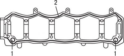
Figure 3.29. Locations of centering pins (1) and application of a layer of sealant (2) on the camshaft bearing housing
Make sure that the centering pins 1 (figure 3.29) are on site.
Apply a bead of 2 AUTOJOINT OR sealant around the entire perimeter of the camshaft bearing housing.
Install the camshaft bearing housings.
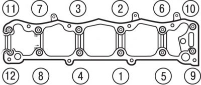
Figure 3.30. Sequence of tightening the camshaft bearing housing bolts
In the sequence shown in the figure 3.30, tighten the camshaft bearing housing bolts to 2 Nm, then tighten to 8 Nm.
Using a tubular pipe of the appropriate diameter, install the camshaft sealing rings.
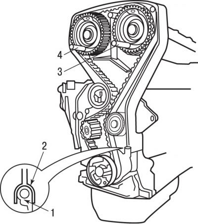
Figure 3.23. When installing the cylinder head, the camshaft timing belt pulleys must be fixed in a certain position with special devices (3 and 4), and the stiffening rib (2) in the lower part of the timing belt casing must fit tightly into the seal holder (1)
Install the rear timing belt cover. Install stiffener 2 (see figure 3.23) at the bottom of the timing belt cover so that it fits tightly into the seal holder 1.
Install the timing belt pulleys onto the camshafts.
Secured with one wrench 1 (see Figure 3.28) to prevent the camshaft from turning, use the second wrench to tighten the timing belt pulley hub mounting bolt to a torque of 80 Nm.
Make sure the camshaft pulley rotates freely on the hub.
Use special tools to prevent the camshaft pulleys and flywheel from turning.
Install the timing belt and adjust its tension.
Install the timing belt covers.
Clean the mating surfaces of the cylinder head covers and install them in place.
The head covers are equipped with composite gaskets that can be used multiple times. Minor damage to the gasket can be partially repaired using a special sealant SILICONE CATEGORIE 2.
Further installation is carried out in the reverse order of removal.