
Gas distribution system
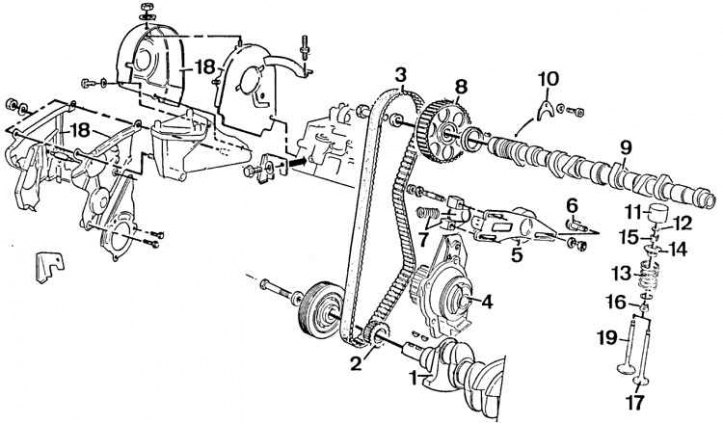
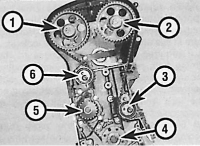
1 - crankshaft; 2 - timing drive pulley; 3 - toothed belt; 4 - coolant pump; 5 - tension roller; 6 - eccentric screw; 7 - tension roller spring; 8 - camshaft pulley; 9 - camshaft; 10 - fastening bracket; 11 - pusher; 12 - adjusting plate; 13 - spring; 14 - plate; 15 - crackers; 16 - oil deflector cap; 17 - exhaust valve; 18 - casing of the gas distribution drive; 19 - inlet valve
The toothed belt drives the camshaft and the coolant pump. If the belt breaks, the pistons can hit the valves and cause serious engine damage. Therefore, it is necessary to replace the belt at the prescribed time or at an earlier date if oil has got on the belt or the belt has uneven wear.
Attention! To accurately set the tension of the toothed belt on models since 1992, it is only possible using a special electronic tool. If the belt tension is approximate, check the tension using a special electronic tool at the first opportunity. Do not drive the vehicle for long distances or operate the engine at high speeds until the belt tension is correct.
Removing the camshaft drive belt is necessary to perform the following operations:
- removal and installation of the cylinder head or camshaft;
- removal and installation of the coolant pump;
- removal and installation of the oil pump drive chain;
- removal and installation of the crankshaft sealing ring;
- valve clearance adjustment.
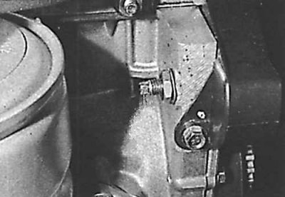
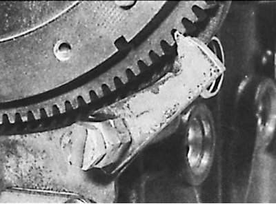
Cam and tip of the eccentric of the tension roller of the camshaft drive belt
Toothed belt location - 1998 models see3 with 16 valves
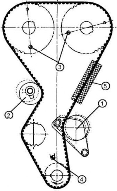
1 - front tension mechanism; 2 - rear pulley of the tension mechanism; 3 - the position of the holes for fixing the camshaft pulleys; 4 - hole for fixing the crankshaft pulley; 5 - area for measuring belt tension (use Peugeot special tool)
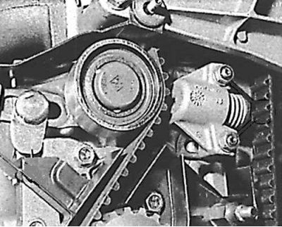
Blocking the camshaft pulleys in the engine 1998 cm3 with 16 valves
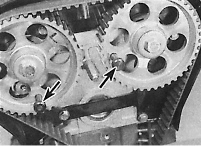
The camshaft pulleys are indicated by arrows.
Removing
Models 1580 cm3 and 1905 cm3 with 8 valves until 1992 with semi-automatic belt tensioner
1. Remove ground wire from battery.
2. Loosen and remove the alternator drive belt.
3. Remove the upper camshaft drive belt cover.
4. Remove side cover.
5. Turn the crankshaft using the pulley bolt so that the timing actuator elements are in a position that allows them to be fixed with rods. To fix these elements, two special steel rods with a diameter of 10 mm and a length of 70 mm should be used (fixture 00163).
6. Insert one rod through the camshaft pulley and the second through the crankshaft pulley (on the thickening there is a hole with a diameter of 10 mm).
7. Remove rods.
8. Remove the bottom plate covering the clutch housing and fix the flywheel (e.g. Facom D 86).
9. Remove the crankshaft pulley.
10. Remove the Facom D 86 tool.
11. Remove the plastic camshaft drive belt covers, bottom left first, then top and bottom right.
12. Loosen the nuts of the tension roller holder and the eccentric control locknut.
13. Using a 6 mm square clamp to control the eccentric, compress the spring together with the tension roller holder.
14. Tighten locknut. The belt is loose.
15. Remove the belt, being careful not to bend it. If the toothed belt is to be reused, the direction of rotation must be noted.
Models 1580 cm3 and 1905 cm3 with 8 valves from 1992 and manual belt tension adjustment and all 1761 cm models3 and 1998 cm3 with 8 valves (differences)
16. To fix the timing gear drive pulleys, use a rod with a diameter of 10 mm on one side and 8 mm on the other.
17. Loosen the bolt securing the timing belt tensioner pulley and turn the pulley clockwise using a square wrench that matches the hole in the pulley hub. Re-tighten the pulley bolt securely.
Models 1905 cm3 with 16 valves (differences)
18. Loosen the front toothed belt tensioner and the rear tensioner pulley bolts. Rotate the front pulley in a clockwise direction using a square wrench to match the hole in the pulley hub and retighten the pulley bolt securely. Rotate the rear pulley counterclockwise in the same way and re-tighten the pulley bolt securely.
19. Check the position of the camshaft pulleys, the crankshaft blocking rods, remove and inspect the toothed belt.
20. Loosen the timing belt pulley rear tensioner bolt, turn the pulley clockwise and re-tighten the pulley bolt.
Models 1998 cm3 with 16 valves (differences)
21. Loosen the bolts securing the two front tensioner assemblies.

22. Loosen the nuts of the tension roller holder and the eccentric control locknut.
23. Move the tensioner pulley to the maximum distance from the belt using a square wrench and remove the toothed belt (see fig. Toothed belt location - 1998 models see3 with 16 valves).
Installing the camshaft drive belt
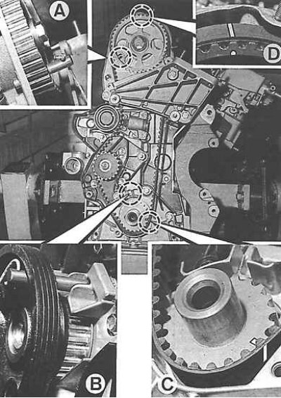
A, B - fixing gears before removing them,
C, D - signs on the timing belt and on the pulleys
Timing Belt Installation Sequence (engines 1905 cm3 with 16 valves)
1, 2, 3, 4, 5, 6 - timing belt installation sequence
Installation
Models 1580 cm3 and 1905 cm3 with 8 valves until 1992 with semi-automatic belt tensioner
1. Before reinstalling the belt, completely clean the toothed belt drive pulleys. Check for smooth rotation of the tensioner pulley.
2. Correctly install the camshaft by inserting a special rod into the appropriate place through the camshaft pulley.
3. Attach the belt to the place of its installation, taking into account the arrows indicating the direction of its movement. Put the belt on the crankshaft pulley.
4. Clean the crankshaft head, pulley and its bolt.
5. Install the pulley on the end of the crankshaft without tightening the fasteners.
6. Inserting a rod through the pulley, check the position of the crankshaft.
7. Place the belt first on the camshaft pulley, then on the idler pulley, and finally on the coolant pump pulley.
8. Loosen the eccentric control jam nut and use a 6 mm square holder to move the eccentric to the withdrawal position (the tension roller will automatically apply tension).
9. Make sure the eccentric cam is in the output position (turned down) and does not pass through the top of the coolant pump disc.
10. Remove both rods.
11. Tighten the idler roller retainer nuts and the eccentric locknut.
12. Using the pulley bolt, turn the engine crankshaft two revolutions so that the piston of cylinder 1 is at TDC (the sign on the flywheel must be opposite the sign "0" ignition adjustment plastics). The gas distribution elements will be in the position shown in fig. Installing the camshaft drive belt.
13. Loosen and tighten nuts (1) and locknut.
14. Turn the crankshaft of the engine to the position of fixation by the rods of the elements of the gas distribution drive. Using two rods, check the gas distribution setting. If the rods are not inserted, then all operations should be repeated.
Attention! It is also possible to install gas distribution using signs (dash) on the belt. The position of these signs must correspond to the signs on the pulleys.
15. Connect ground wire to battery.
Models 1580 cm3 and 1905 cm3 with 8 valves since 1992 and manual belt tension adjustment, as well as all models 1761 cm3 and 1998 cm3 with 8 valves (differences)
16. Install the timing belt as described above.
17. Loosen the tensioner pulley bolt.
18. Install special measuring equipment to measure the belt tension on the front branch of the belt.
19. Adjust so that the initial belt tension is 16±2 units in the 1998 cm model3 with 8 valves and 30±2 units on all other models.
20. Turn the crankshaft several times and re-measure the tension of the front branch of the belt, which should be 44±2 units.
21. If there is no belt tension gauge, tighten the belt so that you can turn the front branch of the belt 90°with your thumb and forefinger. After adjusting the belt tension, tighten all bolts.
Models 1905 cm3 with 16 valves (differences)
22. Loosen the tensioner bolts so that they can be easily turned (see fig. Timing Belt Installation Sequence (engines 1905 cm3 with 16 valves)).
Attention! The belt may have alignment marks in the form of yellow lines to ensure proper installation on both camshaft pulleys and the crankshaft pulley. Two alignment marks with a single line must join the mark on each camshaft pulley. The double line alignment mark must join the crankshaft mark (against keyway).
23. Move the front and rear tensioner pulleys to the toothed belt until they make full contact with it, then tighten the bolts.
24. Move the front tensioner pulley in a counterclockwise direction until the gap is fully selected and tighten the bolts in this position. Install the rear tensioner pulley in the same way.
25. In the presence of measuring equipment, tighten the front branch of the belt to 19 units.
26. Loosen the bolt securing the rear tensioner pulley and turn the pulley clockwise until the tension of the front branch of the belt is 21 units.
27. In the absence of a belt tension gauge, tension the belt so that you can rotate the front branch of the belt 45°between the camshaft pulley and the tensioner pulley with your thumb and forefinger. After adjusting the belt tension, tighten all bolts.
28. Turn the crankshaft several times and re-measure the tension of the front branch of the belt between the camshaft pulley and the tensioner pulley, which should be 45±5 units.
Models 1998 cm3 with 16 valves (differences)
29. Move the tensioner pulley so that the front branch of the belt is tensioned to 45 units, and then set the belt tension to 22±2 units.
30. Loosen the bolt securing the rear pulley of the tension mechanism and turn the pulley counterclockwise until the tension of the front branch of the belt is 32±2 units.
31. In the absence of a belt tension gauge, tension the belt so that you can rotate the front branch of the belt 45°between the camshaft pulley and the tensioner pulley with your thumb and forefinger. After adjusting the belt tension, tighten all bolts.
32. Turn the crankshaft several times and re-measure the tension of the front branch of the belt between the camshaft pulley and the tensioner pulley, which should be 53±2 units.