



Table of contents: Engine 🠇 Crank mechanism 🠇 Gas distribution system 🠇 Lubrication system 🠇 Cooling system 🠇 Power supply system 🠇 Single point fuel injection system 🠇 Multi-point fuel injection systems 🠇 Ignition system 🠇 Tightening moments 🠇
Engine
Cylinder head
The head is made of light alloy and has inserted valve seats and guides. The camshaft bearings are made of the cylinder head material.
| Nominal height: | |
| – engines 1580 cm³, 1761 cm³ and 1905 cm³ (with 8 valves) and 1998 cm³ (with 8 and 16 valves) | 158.93±0.05 mm |
| – 1905 cm³ engine (16 valves) | 132.00±0.05 mm |
| Minimum height after regrinding: | |
| – engines 1580 cm³, 1761 cm³ and 1905 cm³ (with 8 valves) and 1998 cm³ (with 8 and 16 valves) | 158.73 mm |
| – 1905 cm³ engine (16 valves) | 131.80±0.05 mm |
| Maximum tolerance for non-flatness of the lower surface of the head | 0.05 mm |
| Inner diameter of camshaft bearings in cylinder head: | |
| Engines 1580 and 1905 cm³: | |
– 1 | 27,000 – 27,033 mm |
– 2 | 27,500 – 27,533 mm |
– 3 | 28,000 – 28,033 mm |
– 4 | 28,500 – 28,533 mm |
– 5 | 36,000 – 36,039 mm |
Valves
The cylinder head has 8 (or 16) valves installed parallel to each other and at right angles to the lower surface of the head.
Valve sizes
| Valve Plate Diameter: | |
| – inlet valves: | |
| • 1580 cm³ engine | 41.6 mm |
| • 1761 cm³ engine | no data |
| • 1905 cm³ engine (with 8 valves) | 41.8 mm |
| • 1998 cm³ engine (with 8 valves) | 42.6 mm |
| • 1905 cm³ and 1998 cm³ engines (with 16 valves) | 34.7 mm |
| – exhaust valves: | |
| • 1580 cm³ and 1905 cm³ engines | 34.7 mm |
| • 1761 cm³ engine | no data |
| • 1998 cm³ engine (with 8 valves) | 34.5 mm |
| • 1905 cm³ and 1998 cm³ engines (with 16 valves) | 29.7 mm |
| Valve stem diameter: | |
| – inlet valves: | |
| • 1580 cm³ and 1905 cm³ engines (with 8 valves) | 7.83 – 8.13 mm |
| • 1761 cm³ engine | no data |
| • 1998 cm³ engine (with 8 valves) | 7.83 – 7.98 mm |
| • 1905 cm³ and 1998 cm³ engines (with 16 valves) | 6.83 – 6.98 mm |
| – exhaust valves: | |
| • 1580 cm³ and 1905 cm³ engines | 7.83 – 8.13 mm |
| • 1761 cm³ engine | no data |
| • 1998 cm³ engine (with 8 valves) | 7.82 – 8.12 mm |
| • 1905 cm³ and 1998 cm³ engines (with 16 valves) | 6.83 – 6.98 mm |
| Valve length: | |
| – inlet valves: | |
| • 1580 cm³, 1905 cm³ and 1998 cm³ engines (with 8 valves) | 108.79±0.1 mm |
| • 1761 cm³ engine | no data |
| • 1905 cm³ and 1998 cm³ engines (with 16 valves) | 104.48±0.1 mm |
| – exhaust valves: | |
| • 1580 cm³, 1905 cm³ and 1998 cm³ engines (with 8 valves) | 108.37±0.1 mm |
| • 1761 cm³ engine | no data |
| • 1905 cm³ and 1998 cm³ engines (with 16 valves) | 103.00±0.1 mm |
| Valve seating angle | 90° |
| Working edge width | 1.1 mm |
| Valve clearance except for 16-valve engines (on a cold engine): | |
| - inlet valve | 0.20 mm |
| - exhaust valve | 0.40 mm |
Attention! Exhaust valves are not ground.
Valve seats
The valve seats are inserted into the cylinder head and are not replaceable.
Valve guides
The valve guides are insertable and made of cast iron or brass.
| O.D: | |
| - nominal | 13 0.08 or 13 0.05 mm |
| - repair size | 13.13±0.011 mm; 13.29±0.011 mm; 13.59±0.011 mm |
Valve springs
One spring is used per valve. Inlet and outlet valves have identical springs.
Characteristics of springs
| XU5 Engine: | |
| - designation | green |
| - height: | |
| • at a load of 400 N | 42.5 mm |
| • under load of 800 N | 31.0 mm |
| XU9 Engine: | |
| - designation | black |
| - height: | |
| • at a load of 410 N | 40.5 mm |
| • at a load of 860 N | 30.0 mm |
| - designation | gray |
| - height: | |
| • at a load of 395 N | 41.5 mm |
| • at a load of 780 N | 31.0 mm |
Pushers
The tappets move directly in the cylinder head material. Adjustment of the valve clearance is based on the installation of adjusting plates of the appropriate thickness between the valve stems and tappets.
Engines with 16 valves have hydraulic tappets that provide automatic adjustment of valve clearances.
| Diameter of plates | 13.5 mm |
| Plate thickness: | |
| – every 0.025 mm | from 1,650 to 3,000 mm |
| – every 0.075 mm | from 3.025 to 3.550 mm |
| – every 0.025 mm | from 3.575 to 4.000 mm |
Cylinder head gasket
| Brand | Reinz or Curty |
| Gasket thickness: | |
| - nominal | 1.2 mm |
| - for reground head | 1.4 mm (identification by means of a cutout and a 4 mm diameter hole on the projection at one end of the gasket) |
| Installation | protrusion on the flywheel side |
Engine cylinder block
Engine block on models with a working volume of 1580 cm³, 1761 cm³ and 1905 cm³ (with 8 and 16 valves) made of light alloy and has inserted wet cylinder liners. On models with a working volume of 1998 cm³ (with 8 and 16 valves), the cylinders are made directly in the body of the cylinder block.
Crankshaft main bearing surface diameter: 63.708–63.727 mm.
Cylinder liners
The cylinder liners are of the clamping type and the sealing is ensured by a round sealing ring.
Matching of pairs of liners and pistons is mandatory: letter designations are applied to the piston bottoms and to the upper edges of the liners.
| Engine cylinder bore diameter: | |
| – engines 1580 cm³, 1761 cm³ and 1905 cm³ (with 8 valves): | |
| • Group A | from 83,000 to 83,010 mm |
| • Group B | from 83.010 to 83.020 mm |
| • Group C | from 83.020 to 83.030 mm |
| – 1998 cm³ engines (with 8 valves): | |
| • Group A | from 86,000 to 83,010 mm |
| • Group B | from 86.250 to 86.268 mm |
| • Group C | from 86.600 to 86.618 mm |
| – 1905 cm³ engine (with 16 valves): | |
| • Group A | from 83,000 to 83,010 mm |
| • Group B | from 83.010 to 83.020 mm |
| • Group C | from 83.020 to 83.030 mm |
| Sleeve protrusion relative to cylinder block, except 1998 cm³ (measured without O-ring) | 0.03 – 0.10 mm |
| Maximum difference between any two cases: | |
| – 8-valve engines | 0.05 mm |
| – 16-valve engines | 0.02 mm |
Crank mechanism
Crankshaft
The crankshaft is made of cast iron and rests on five main bearings.
| Longitudinal clearance of the crankshaft: | |
| – 8-valve engines | from 0.07 to 0.32 mm |
| – 16-valve engines | from 0.07 to 0.27 mm |
| Main journal diameter: | |
| – engines 1580 cm³, 1905 cm³ and 1998 cm³: | |
| • standard | from 59,981 to 60,000 mm |
| • repair | from 59.681 to 59.700 mm |
| – 1761 cm³ engine | no data |
| Connecting rod journal diameter: | |
| – engines 1580 cm³, 1905 cm³ and 1998 cm³: | |
| • standard | from 49,984 to 50,000 mm |
| • repair | from 49.684 to 49.700 mm |
| – 1761 cm³ engine | no data |
| Operating clearance in main bearings: | |
| – engines 1580 cm³, 1761 cm³ and 1905 cm³ | from 0.025 to 0.050 mm |
| – 1998 cm³ engines | from 0.038 to 0.069 mm |
| Working clearance in connecting rod bearings (all models) | from 0.025 to 0.050 mm |
Main bearing shells
| Thickness: | |
| - nominal | 1.842±0.003 mm |
| - repair size | 1.992±0.003 mm |
Connecting rod bearing shells
| Engine 1580 cm³: | |
| – nominal thickness | 1.812±0.01 mm |
| - repair size | 1.962±0.01 mm |
| Engine 1905 cm³: | |
| – nominal thickness | 1.833±0.003 mm |
| - repair size | 1.983±0.003 mm |
Thrust half rings (axial plain bearings)
| Thickness: | |
| - nominal | 2.30 or 2.35 mm |
| - repair dimensions | 2.40, 2.45 and 2.50 mm |
Flywheel
The flywheel is bolted to the crankshaft with eight bolts.
Number of teeth on the ring gear: 136.
Connecting rods
The connecting rods are forged from steel. They have thin-walled liners made from aluminum-tin alloy.
| Distance between axles: | |
| – 1580 cm³ engine | 150.5 mm |
| – 1905 cm³ engine | 143.0 mm |
| Connecting rod upper head bore diameter | 22±0.029 mm |
| Connecting rod lower head bore diameter: | |
| – 1580 cm³ engine | 48.655±0.016 mm |
| – 1905 cm³ engine | 53.695±0.013 mm |
| Maximum weight difference between connecting rods of the same engine: | |
| – engines 1580 cm³, 1761 cm³ and 1905 cm³ | 13 g |
| – 1998 cm³ engine | 7.0 g |
Pistons
The pistons are made of light alloy. The pin is fixed in the connecting rod with tension, and in the piston - freely.
Installation: the arrow on the piston bottom must point towards the camshaft drive.
Matching pairs of liners and pistons: 3 groups of pistons: A, B and C correspond to 3 groups of cylinder liners, designated by the same letters (on the upper edges).
Piston diameter
| Engines 1580 cm³, 1761 cm³ and 1905 cm³ (with 8 valves): | |
| - Group A | 82.960±0.007 mm |
| - Group B | 82.970±0.007 mm |
| - Group C | 82.980±0.007 mm |
| 1905 cc 16 valve engine: | |
| - Group A | from 82.963 to 82.977 mm |
| - Group B | from 82.973 to 82.987 mm |
| - Group C | from 82.983 to 82.997 mm |
Piston rings
| Gaps in the lock: | |
| – upper sealing ring: | |
| • 1580 cm³ engine | from 0.4 to 0.6 mm |
| • 1905 cm³ engine | from 0.2 to 0.4 mm |
| • 1761 cm³ and 1998 cm³ engines | from 0.3 to 0.5 mm |
| – second sealing ring: | |
| • 1580 cm³ and 1905 cm³ engines | from 0.15 to 0.35 mm |
| • 1761 cm³ and 1998 cm³ engines | from 0.3 to 0.5 mm |
| Oil scraper ring, all models | from 0.3 to 0.5 mm |
As spare parts, only UFLEX rings are now supplied, which replaced the previously used rings. They are installed without a gap on the lock. Their installation requires strong compression, as well as greater attention and accuracy, so as not to break the rings.
Piston pins
The steel pins are ground. They are fastened loosely in the pistons and with tension in the connecting rods. There are 3 groups of pins corresponding to the piston groups, marked with colored paint.
On 16-valve models, the piston pins have a sliding fit in the connecting rod and are secured with retaining rings.
Correspondence of the marking on the piston to the color of the mark on the pin
1 | blue |
2 | white |
3 | red |
Gas distribution system
The valve timing system consists of a camshaft mounted in the cylinder head, secured in five bearings and driven by a toothed belt. The camshaft controls the operation of the valves by means of tappets equipped with clearance adjustment plates.
The valve timing is determined with a theoretical gap of 1 mm.
| XU5 Engine: | |
| – opening of the intake valve | 6° 30' lead |
| - closing the intake valve | 31° 18' |
| – opening of the exhaust valve | 41° 18' |
| - closing the exhaust valve | 3° 30' |
| XU9 Engine: | |
| – opening of the intake valve | 3° lag |
| - closing the intake valve | 46° |
| – opening of the exhaust valve | 40° 8' |
| - closing the exhaust valve | 2° 2' |
Camshaft
The camshaft is mounted in the cylinder head and secured in five bearings made directly in the cylinder head material and is driven by a toothed belt.
| Camshaft bearing diameter (engines 1580 cm³ and 1905 cm³: | |
| – 1 | 26,980 – 26,959 mm |
| – 2 | 27,480 – 27,459 mm |
| – 3 | 27,980 – 27,959 mm |
| – 4 | 28,480 – 28,459 mm |
| – 5 | 35.975 – 35.950 mm |
Toothed belt
Brand: Uniroyal Powergrip 58113 x 17.
The belt tension is provided by a roller tensioner.
Lubrication system
Lubrication under pressure is provided by an oil pump driven by a chain from the crankshaft.
The oil pressure sensor is adjusted to 0.08 MPa.
Since April 1987, the oil pump has been 5 mm higher. The spacer element located between the pump and the cylinder block has been removed, as well as the intermediate sleeve attached to the cylinder block.
A new pump can be installed in place of the old one, provided that the intermediate element is removed and washers are placed under the pump mounting bolts.
The length of the drive chain remains unchanged.
Oil pump
The gear oil pump body is made of light alloy.
| Oil pressure at 90°C: | |
| – XU5 engine | 0.35 MPa at 4000 rpm |
| – XU7 engine | 0.53 MPa at 4000 rpm |
| – XU9 engine | 0.41 MPa at 4000 rpm |
| – XU10 engine | 0.52 MPa at 4000 rpm |
Oil filter
The oil filter with replaceable element has a bypass valve connected.
Brand and type: Purflux LS 468 A.
Motor oil
| Quantity: | |
| – XU engine (8 valves) no filter | 4.5 dm³ |
| – XU engine (8 valves) with filter | 5.0 dm³ |
| – XU engine (16 valves) no filter | 5.0 dm³ |
| – XU engine (16 valves) with filter | 5.3 dm³ |
| Recommended type | SAE 10W/40 or 15W/50, API SF, CCMC G3, Esso Super Oil 10W/40 or Shell Puissance 5 SAE 10W/40 |
Cooling system
The engine is cooled under pressure (0.1 MPa) with a mixture of water and a special antifreeze. The cooling system includes: a radiator, a coolant pump, an expansion tank and a fan with an electric motor.
Coolant pump
The centrifugal coolant pump is installed in the engine cylinder block and is driven by a toothed belt.
Radiator
The radiator has a horizontal flow aluminum core.
Brand: Chausson or Valeo.
Thermostat
| Opening start temperature: | |
| – 1580 cm³ engines: | |
| • all engines except B2A (XU52C) and BDY (XU5M) | 88°C |
| • engines B2A (XU52C) and BDY (XU5M) | 82°C |
| – 1761 cm³ engines | 88°C |
| – 1905 cm³ engines: | |
| • all engines except D2H (XU92C), D5A (XU92C) and D6D (XU9J2) | 88°C |
| • engines D2H (XU92C), D5A (XU92C) and D6D (XU9J2) | 82°C |
| – 1998 cm³ engines: | |
| • RFX (XU10J2C) and RFY (XU10J4) engines | 89°C |
| • RGZ engine (XU10J4) | 88°C |
| Full opening temperature: | |
| – 1580 cm³ engines: | |
| • all engines except B2A (XU52C), B3B (XU51C) and BDY (XU5M) | 100°C |
| • B2A engine (XU52C) | 93°C |
| • B3B engine (XU51C) | 102°C |
| • BDY engine (XU5M) | 94°C |
| – 1761 cm³ engines | 100°C |
| – 1905 cm³ engines: | |
| • all engines except D2H (XU92C), D5A (XU92C) and D6D (XU9J2) | 100°C |
| • engines D2H (XU92C) and D5A (XU92C) | 93°C |
| • D6D engine (XU9J2) | 94°C |
| – 1998 cm³ engines: | |
| • RFX (XU10J2C) and RFY (XU10J4) engines | 101°C |
| • RGZ engine (XU10J4) | 100°C |
Fan
The fan is driven by an electric motor and has two speeds.
Temperature | 1 speed | 2 speed |
| Inclusions | 90°C | 94°C |
| Shutdowns | 86°C | 90°C |
Temperature sensor
Temperature for switching on the control lamp: 110°C.
Coolant
Quantity | 6.6 dm³ |
| Recommended type | a mixture of water and antifreeze in a 1:1 ratio (up to -17°C) |
| Frequency of replacement of coolant and flushing of the cooling circuit | every 2 years |
Power supply system
Fuel tank
The fuel tank is made of artificial material and is installed under the floor in front of the rear axle.
Volume: 70 dm³ (petrol 98 or unleaded petrol Eurosuper 95).
Fuel pump
The mechanical, diaphragm fuel pump is driven by the camshaft eccentric.
Air filter
| View | dry filter |
| Brand and type | Mann Microtop C 33 156 |
Carburetor
The two-chamber carburetor has an automatic starting device, pneumatic enrichment at maximum power and a lock for the second chamber when the engine is cold.
Brand and type:
- xU5 engine: Solex 34/34 Z1 designation 446/460;
- engine XU9: Solex 34/34 Z1 designation 447/462.
Carburetor type | Solex 34/34 Z1 446/460 | Solex 34/34 Z1 447/462 | ||
1 camera | 2 camera | 1 camera | 2 camera | |
| Diffuser diameter (mm) | 25 | 27 | 26 | 27 |
| Main fuel jet | 1,150 | 1,275 | 1,200 | 1,225 |
| Main air jet | 1,450 | 1,600 | 1,500 | 1,600 |
| Main air jet | 18 | ZC | BZ | ZC |
| Idle fuel jet | 0,46 | 0,90 | 0,45 | 0,90 |
| Idle air jet | 1,45 | 1,45 | 1,45 | 1,45 |
| Calibrated enrichment device jet | 0,5 | 0,5 | ||
| Needle valve seat diameter | 1,8 | 1,8 | ||
| Accelerator pump sprayer | 0,35 | 0,35 | 0,40 | 0,40 |
| Opening 2 chambers | – | 9° | – | 9° |
| Fuel level in float chamber (mm) | 33,5 | 33,5 | ||
| Fast Idle Speed (rpm) | 2450 – 2600 | 2450 – 2600 | ||
| Idle speed (rpm) | 750±100 | 750±100 | ||
| CO content (%) | 0,8 – 1,5 | 0,8 – 1,5 | ||
| CO₂ content (%) | 10 | 10 | ||
Single point fuel injection system
| System type: | |
| – XU5 engine (BDZ and BDY) | Magneti Marelli G5 single point |
| – XU5 engine (BDY) | MagnetiMarelli G6 single point |
| – XU9 engine (DDZ) | Solex Fenix IB single point |
Fuel pump
Electric type, external (early models) or internal (later models).
| Pump feed pressure: | |
| – injection system Fenix IB, MM G5 and MM G6 | 0.7 – 0.8 bar |
| – Bosch MA3.0 injection system | 1.0±0.1 bar |
| Pump performance: | |
| – Fenix IB and Bosch MA3 injection system | 0 – 370 cm³ in 15 seconds |
| – injection system MM G5 and G6 | 360 cm³ in 15 seconds |
Multi-point fuel injection systems
| System type: | |
| – engine XU5 (BFZ), XU7 (LFZ), XU10 (RFX), XU10 (R6D) | Magnett Marelli 8P multipoint |
| – XU5 engine (BFZ) | Sagern-Lucas 4GJ multipoint |
| – XU7 engine (LFZ) | Bosch Motronic MP5. l multipoint |
| – XU9 engine (D6A and D6D) | Bosch L3. l-Jetronic multipoint |
| – XU9 engine (D6D) | Bosch Motronic MP3. l multipoint |
| – XU9 engine (DKZ and DFZ) | Bosch LU2-JETRONIC multipoint |
| – XU9 engine (DKZ and DFV), XU9 (DFW with 16 valves) | Bosch Motronic MI. 3 multipoint |
| – XU9 engine (D6C with 16 valves) | Bosch Motronic ML4. l multipoint |
| – XU10 engine (RFY 16 valves), XUIO (RFT) | Bosch Motronic MP3. 2 multipoint |
Fuel pump
Electric type, external (early models) or internal (later models).
| Pressure generated by the fuel pump at the specified idle speed: | |
| – Bosch L3 system. l | 2.5 bar |
| – other Bosch systems | 3.0±0.2 bar |
| – Magneti Marlli system | 2.5±0.2 bar |
| Idle speed: | |
| – Boscn L3 system | 925±25 rpm |
| - other systems | 850±50 rpm |
Recommended fuel
| Minimum octane number: | |
| – engines TU3 (KIA), TU3A (KIG), XU92C (D2D), XU9J2 (DGA), XU9J4 (D6C), XU52C (B2A) | 97 |
| - other models | 95 |
Ignition system
| Models with carburetor L3. l-Jetronlc and LU2-JETRONIC | contactless ignition system |
| Other models except XU10J4 with 16 valves | eCU controlled composite ignition system |
| Models XU10J4 (with 16 valves) | direct ignition system controlled by ECU |
The transistor contactless ignition system has a distributor with a built-in Hall effect sensor, as well as regulators - centrifugal and vacuum.
Distributor
| Brand | Bosch or Ducellier |
| Designation of characteristics: | |
| – XU5 engine | C 005 and D 020 |
| – XU9 engine | C 053 and D 040 |
| Initial ignition timing angle: | |
| – XU5 (B2A) and XU9 (D2H) engines with carburetor | 10° before TDC at 750 rpm |
| – models with fuel injection system: | |
| • L3. l-Jetronic | 5° before TDC at 900 rpm |
| • LU2- Jetronic | 10° before TDC at 850 rpm |
| - all other models | controlled by the ECU (not regulated) |
| Firing order | 1–3–4–2 (No. 1 from the camshaft drive side) |
Caution: When using low octane fuel, the ignition timing must be reduced by 3° on the following engines: XU92C (D2D), XU9J2 (D6A), XU9J4 (D6C) and XU52C (B2A).
Ignition Advance Characteristics (xU9 engine)
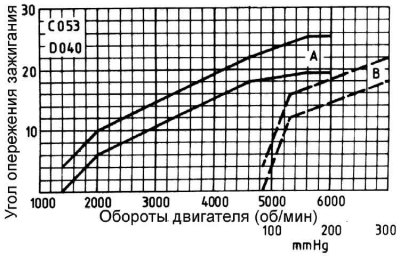
A - centrifugal regulator
B – vacuum regulator
During the test on the stand (ignition distributor removed) values must be reduced by half. When checking the distributor installed in the car, it is necessary to add the value of the initial ignition advance angle.
Ignition Advance Characteristics (xU5 engine)
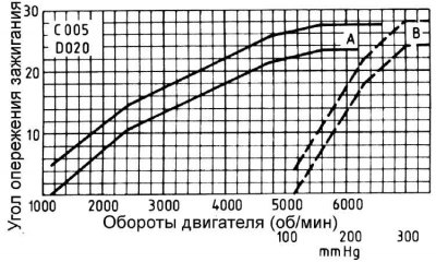
A - centrifugal regulator
B – vacuum regulator
During the test on the stand (ignition distributor removed) values must be reduced by half. When checking the distributor installed in the car, it is necessary to add the value of the initial ignition advance angle.
Ignition coil
| Brand | Bosch or Ducellier |
| Winding resistance: | |
| - primary | 0.7 Ohm |
| - secondary | 6.6 kOhm |
Spark plugs
Spark plugs have a conical seal (do not have a gasket).
Brand and type: Champion C7YCX or Eyquem FC 62 LS.
Tightening moments
XU5, XU7 and XU9 engines
| Cylinder head: | |
| - Stage 1 | tightening torque 60 Nm |
| – Stage 2 | unscrewing and then tightening with a torque of 20 Nm |
| – Stage 3: | |
| • Torx bolts | tightening to an angle of 300° |
| • hex bolts | tightening at an angle of 120° |
| Timing Belt Cover | 8 Nm |
| Timing Belt Tensioner Pulley Bolt | 20 Nm |
| Oil pump | 13 Nm |
| Lower connecting rod bearing cap: | |
| - Stage 1 | tightening torque 40 Nm |
| – Stage 2 | unscrewing and then tightening with a torque of 20 Nm |
| – Stage 3 | tightening at an angle of 70° |
| Front seal | 16 Nm |
| Main bearing caps | 52.5 Nm |
| Side bolts of main bearing caps | 22 Nm |
| Crankshaft pulley: | 120 Nm |
| Flywheel | 50 Nm |
| Camshaft pulley | 80 Nm |
| Camshaft bearings | 15 Nm |
| Oil pan | 20 Nm |
| Cylinder head cover | 10 Nm |
| Spark plugs | 17.5 Nm |
XU10 Engines
| Cylinder head cover | 10 Nm |
| Timing Belt Cover | 8 Nm |
| Crankshaft pulley | 110 Nm |
| Timing Belt Tensioner Mechanism | 20 Nm |
| Cylinder head mounting bolts: | |
| - Stage 1 | tightening torque 35 Nm |
| – Stage 2 | tightening torque 70 Nm |
| – Stage 3 | tightening to an angle of 160° |
| Oil pan | 16 Nm |
| Oil pump | 13 Nm |
| Lower connecting rod bearing cap: | |
| - Stage 1 | tightening torque 40 Nm |
| – Stage 2 | unscrewing and then tightening with a torque of 20 Nm |
| – Stage 3 | tightening at an angle of 70° |