



Table of contents: Examination 🠇 Adjustment 🠇
Valve clearance should only be adjusted if incorrect adjustment is detected, valves are replaced or ground in, or tappets or camshafts are replaced.
Examination
Models 1905 cc and 1998 cc with 16 valves
The 1905cc and 1998cc 16-valve models feature automatic valve clearance adjustment.
Other models
The valve clearance is checked with a feeler gauge between the cam and the tappet.
Before checking the clearance, the engine must cool down for at least 2 hours with the hood open.
(Text taken from the website: PeugeotBook.ru)
Example of calculating the thickness of the valve adjusting plate
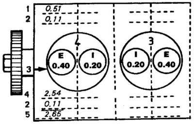
I – inlet valve, E – outlet valve, 1 – measured clearance, 2 – difference between 1 and 3, 3 – required clearance, 4 – thickness of installed plate, 5 – thickness of new plate
Valve arrangement
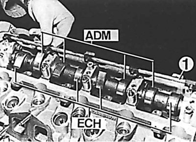
ADM – intake valves,
ECH – exhaust valves,
1 – oil line for lubricating the camshaft bearings
1. Remove the cylinder head cover.
2. Draw a diagram of the engine on paper. Show the position of each valve along with the valve clearance indicated. Above each valve, draw two lines to record (1) the actual clearance and (2) the amount of adjustment required.
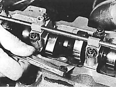
3. Turn the crankshaft until the intake valve of cylinder No.1 is completely closed (from the flywheel side), i.e. the camshaft cam should be directed upwards. Use a feeler gauge to measure the gap between the cam and the tappet and record it on line 1.
4. Repeat the measurement for the remaining seven valves, rotating the crankshaft as necessary so that the cam in question always points upward.
5. Calculate the difference between each measured gap and the required gap and record it on line 2.
6. If the measured gap does not correspond to the required one, it is necessary to make adjustments.
Valve clearance (cold engine):
- inlet valve: 0.20 mm;
- outlet valve: 0.40 mm;
- tolerance: ±0.05 mm.
One of the methods of checking valve clearance sequence
| Bring the exhaust valve of cylinder No. to full opening | Adjust the clearance of the following valves |
| 1 | intake 3 cyl., exhaust 4 cyl. |
| 2 | intake 4 cyl., outlet 2 cyl. |
| 3 | intake 2 cyl., exhaust 1 cyl. |
| 4 | intake 1 cyl., outlet 3 cyl. |
Adjustment
1. Check the valve clearances according to the above method and record the measured clearance values.
2. Remove the camshaft drive belt.
3. Remove the camshaft bearing lubrication oil line, distributor, bearing mounting bolt No.1 and camshaft flange.
4. Insert a special steel rod with a diameter of 10 mm (length 70 mm) into the camshaft pulley and unscrew the bolt securing this pulley.
5. Unscrew the bolt under the coolant pipe mounting bracket (the liquid from the cooling system should not be drained) and remove the sheet casing.
6. Unscrew the camshaft bearing cap fastening nuts in order.
7. Separate cover #1 (near the distributor) from its side seal and remove the remaining covers (covers No.2 and 4 are marked).
8. Remove the camshaft from the right side.
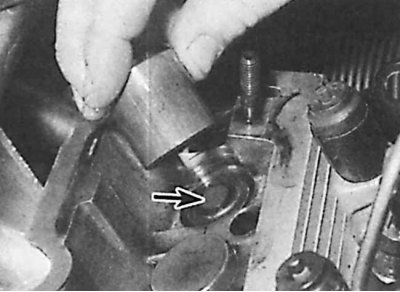
9. Remove the tappets and install them in a row in order (the pusher is shown by the arrow).
10. Remove the adjusting plates and measure their thickness.
11. Determine the required thickness of the adjusting plates:
- if the measured gap value is too small, then a plate of a smaller thickness should be installed, by the value recorded on line 2;
- if the measured gap value is too large, then a plate of greater thickness should be installed, by the value recorded on line 2.
12. Draw three more lines on the drawing below each valve.
13. On line (4) plot the measured thickness of the plates that were removed from the engine, then add or subtract the difference from line (2) to obtain the required thickness of the plates, and write it on line (5).
Attention! After replacing one of the valve timing system components or after grinding the valves, 8 adjusting plates with a thickness of at least 2.15 mm must be installed.
14. Install pushers with plates of the required thickness.
15. Install the camshaft and bearing caps. The installation order must be followed. Tighten the bearing caps to 15 Nm.
16. Turn the camshaft using the pulley bolt and check the valve clearance. If the clearance is incorrect, the adjustment must be repeated.
17. Check if the crankshaft is in the valve timing position.
18. Replace the side seal of bearing cap No.1, lubricate the two surfaces of the seal and the lower connection with sealing paste.
19. Install the camshaft mounting flange.
20. Install a new drive side camshaft seal (fixture 7.0153 E together with bolt and pulley gasket).
21. Install the sheet metal casing without tightening the fasteners.
22. Center the casing using a 10mm diameter rod.
23. Install the camshaft pulley and insert the timing system installation rod into the appropriate place.
24. Tighten the pulley mounting bolt to 80 Nm.
25. Screw in the casing mounting bolts.
26. Install the camshaft bearing lubrication channel, distributor, cylinder head cover and connect the wires.
27. Install the camshaft drive belt.
28. Adjust the ignition timing.