Table of contents: Fuel injection pump (the latest…🠇 Lucas Roto- or Con-Diesel fuel…🠇 Lucas CAV/Roto-Diesel fuel injection…🠇
Caution: The maximum engine speed and intermediate pressure adjustment screws, as well as the plugs closing the inspection holes for adjusting the injection timing, are closed and sealed by the manufacturer during assembly. If the car is still under warranty, these seals cannot be removed. Do not attempt to adjust the pump timing unless you have sufficiently accurate measuring instruments.
1. Disconnect the negative cable from the battery.
2. Cover the generator with a plastic bag to protect it from fuel splashes.
3. Apply the handbrake and jack up the front right wheel of the car until it is off the ground. Support the car and engage 4th or 5th gear. This will allow the engine to be turned using the right front wheel.
4. Disconnect the wire from the glow plug of cylinder No. 4 (from the timing belt side) and unscrew the spark plug. Please note that the injection timing is adjusted with piston No. 4 in the TDC position on the compression stroke (i.e. piston No. 1 is at TDC with the valves changing their position).
5. You will need two dial gauges to check the position of piston No. 4 and the fuel injection pump. You will also need magnetic stands or brackets to mount the gauges in the correct locations on the engine.
6. Unscrew and remove the plug on the cylinder head next to injector No. 4 (see photo).
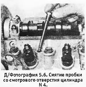
7. Turn the engine forward until pressure is felt in cylinder No. 4, indicating that piston No. 4 has begun to rise on the compression stroke.
8. Place the dial gauge over the inspection hole and attach its probe to the piston (see photo).
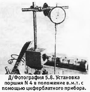
9. Turn the engine forward again until the instrument shows the maximum lift of piston No. 4. To check, turn the engine slightly forward and backward until the piston reaches the top position, and set the instrument to zero.
10. Loosen the lower of the two large side plugs on the fuel injection pump. Place a small container under the plug, then remove the plug and collect any spilled fuel in the container (see photo).

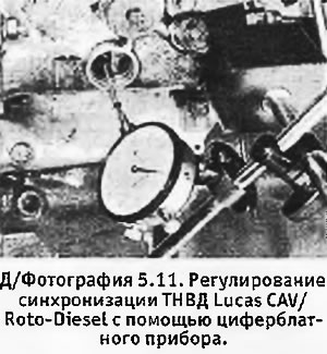
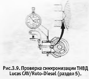
11. Under the plug there is a guide for the dial gauge probe. Insert the probe and connect it to a dial gauge positioned directly over the hole (see photo and Figure 3.9). Please note that the probe must have a pointed end to ensure that it fits completely into the groove on the pump rotor.
 |
 |
12. Turn the engine back approximately 1/8 of a turn or until piston No. 4 moves 4.0 mm down the cylinder. Now slowly rotate it forward, monitoring the dial gauge on the high-pressure fuel pump. After the probe reaches the bottom of the rotor groove and then rises 0.01-0.02 mm, check that the upper dial gauge reads 2.26 ± 0.05 mm before TDC. If other readings are obtained, proceed as follows.
13. Check the accuracy of the upper dial instrument zero setting by repeating the procedure specified in paragraph 9.
14. Turn the engine back approximately 1/8 of a turn or until piston No. 4 moves 4.0 mm down the cylinder. Now slowly turn it forward so that piston No. 4 reaches the position 2.26±0.05 mm before TDC
15. Unscrew the nuts of the fittings and disconnect the fuel injector pipes from the high-pressure fuel pump. Loosen the fuel injection pump mounting nuts and bolts.
16. Turn the pump body so that the probe rests on the bottom of the groove on the pump rotor. Set the dial gauge to zero and turn the pump clockwise (if you look from the side of the fuel injector pipes) so that the probe rises by 0.02 mm.
17. Tighten the pump mounting nuts and bolts, ensuring that the dial gauge does not show any movement.
Original is contained on the portal www.PEUGEOTBOOK.ru
18. Check the pump synchronization again as described in paragraph 12.
19. Remove the dial instruments and replace the plugs. Connect the fuel pipes to the injectors and tighten the fitting nuts.
20. Install the glow plug in place and connect the wire to it.
21. Lower the car to the ground and connect the negative cable to the battery. Remove the plastic bag from the generator.
22. Pump fuel into the system (see section 17).
Fuel injection pump (the latest Lucas CAV/Roto-Diesel models)
1. Since 1987, modified high-pressure fuel pumps have been gradually installed. The new type pump can be identified by a white plastic disc on the front surface, which indicates the value for adjusting the pump's static synchronization (see photo). The blue disk indicates that this pump has been refurbished to factory specifications. The setting value for adjusting the pump may also be indicated on a plastic plate attached to the pump control lever.
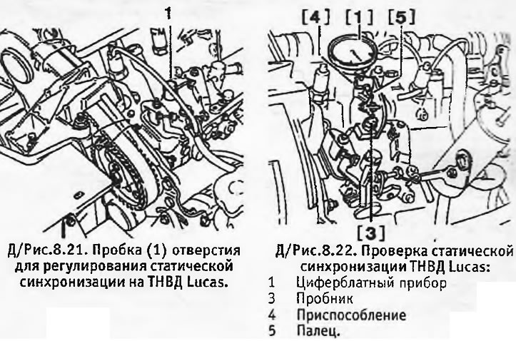
2. The new type pump is adjusted to the TDC position. Only one dial gauge is required, but you will have to make your own device in the form of a bent rod, which will be inserted into the hole for setting the TDC. For this purpose, we used an M8 bolt, the thread of which was removed with a file attached to a welding electrode (see photo). Alternatively, with the starter removed, you can use a drill or a straight rod (see photo 22.26).
3. Prepare for work as described above in paragraphs 1-3.
4. Turn the engine so that piston No. 4 (from the timing belt side) reached the TDC position on the compression stroke. To verify this, remove the glow plug of cylinder No. 4 or the TDC hole plug located next to injector No. 4 (see photo 6.85) and make sure that the pressure in the cylinder increases. Alternatively, you can remove the valve cover and determine the moment when the valves of cylinder No. 1 begin to change their position (the intake valve begins to open and the exhaust valve begins to close).
5. Insert the TDC setting tool into the hole in the left end of the cylinder block (behind the place where the starter is). Turn the engine back and forth slightly so that the device fits into the hole in the flywheel, and leave it in this position.
6. Remove the plug from the inspection hole at the top of the pump. Position the dial gauge so that it shows the movement of the probe inserted into this hole. To hold the magnetic stand of the dial gauge in place, you can use a steel plate bolted to the engine mount or the valve cover (see photos).
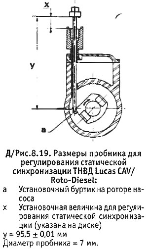
7. Make a tester according to the dimensions shown in Figure 8.19. Insert the tester into the inspection hole so that its end fits onto the mounting flange on the pump rotor and turn the dial gauge so that its readings can be taken.
8. Remove the TDC setting tool and turn the engine back approximately 1/4 turn. In this position, set the dial gauge to zero.
9. Slowly turn the engine forward so that the TDC setting tool can be inserted again. Check the dial gauge reading: it should give the value indicated on the pump disc (±0.04 mm).
10. If the device does not give the required value, do the following.
11. Disconnect the fuel injector pipes from the pump. Loosen the pump mounting nuts and bolts and turn the pump housing away from the engine. Set the dial gauge to zero.
12. With the engine still at TDC, slowly rotate the pump back toward the engine until the dial gauge shows the value indicated on the disc. In this position, tighten the pump mounting nuts and bolts. Remove the TDC setting tool and check the pump synchronization as described above.
13. After completing the adjustment, reconnect the fuel lines of the injectors, remove the dial gauge and the TDC setting device, and install the inspection hole plug in place.
14. Reinstall the other removed and disconnected parts, remove the plastic bag from the generator and lower the machine to the ground.
Lucas Roto- or Con-Diesel fuel injection pump on 405 models
1. The procedure is similar to that described earlier for the latest Lucas CAV/Roto-Kesel fuel injection pump models.
Lucas CAV/Roto-Diesel fuel injection pump dust shield
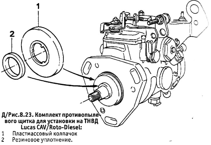
1. Since April 1988, the Lucas CAV/Roto-Diesel injection pump has been fitted with a dust shield to protect the front bearing seal.
2. If for some reason you are going to remove the old pump, you should purchase a dust shield, which is sold in a special kit, and install the pump with the dust shield.