
Warning. Do not attempt injection advance adjustment procedures without accurate instruments. Appropriate special tools for adjusting the injection advance of the pump can be purchased from major auto parts stores or your Peugeot/Citroen dealer. Please read the safety precautions before starting work paragraph 1 this chapter.
Note. A dial indicator is required to check the injection advance of the high pressure fuel pump (Peugeot/Citroen special tool No. 2437-T) together with a special installation probe and support bracket (Peugeot/Citroen Special Tool No. 4O93-TJ) (pic. 7.4). Without this equipment (or the corresponding alternative) The procedure for checking and adjusting the injection advance of the high pressure fuel pump should be carried out by a Peugeot/Citroen dealer or another person who has the appropriate equipment.
1. If the fuel injection advance is checked without removing the pump from the engine, and not during the pump installation procedure, disconnect the wire «masses» from battery (see «Disconnecting the battery») and cover the generator rotor with a clean cloth or plastic bag to protect it from possible fuel spillage. Remove the fuel injector lines as described in paragraph 5.
2. Align the engine/camshaft assembly alignment marks (see chapter 2B), to lock the crankshaft. Remove the crankshaft locking tool and then turn the crankshaft back (counterclock-wise) about a quarter of a turn.
3. Unscrew the process plug from the guide on the top of the pump housing and remove the sealing washer (pic. 7.3). Insert the special installation probe into the guide, making sure that it correctly fits the surface of the sealing washer on the guide.
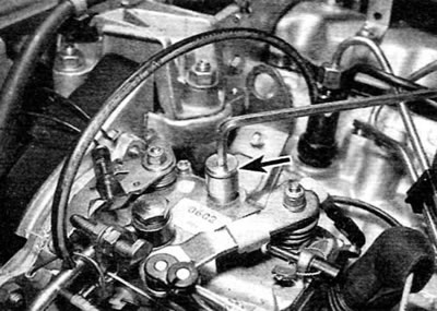
Pic. 7.3. Removing the technological plug from the hole for adjusting the injection advance of the high pressure fuel pump (Lucas pump)
Note. To ensure measurement accuracy, the feeler gauge must fit on the surface of the guide sealing washer and not on the top edge of the guide.
4. Attach the bracket to the pump rail and securely attach the dial indicator to the bracket so that its tip makes contact with the bracket linkage (pic. 7.4). Position the indicator so that its plunger is in the middle of the stroke, and then reset the reading to zero.
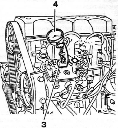
Pic. 7.4. Dial gauge for adjusting the injection advance of the high pressure fuel pump (4) and matching support bracket (3), attached to the high pressure fuel pump
5. Slowly turn the crankshaft in the correct direction of rotation (forward arrow) long enough to reinstall the crankshaft locking tool.
6. With the crankshaft locked, read the indicator; the reading must match the value indicated on the pump (there is a tolerance of +0.04 mm). The injection advance value can be indicated on a plastic disc attached to the front of the pump, or alternatively on a tag attached to the pump control knob (pic. 7.6).
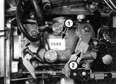
Pic. 7.6. High Pressure Injection Pump Injection Advances Specified on the Label (1) and tag (2) (Lucas pump)
7. If adjustment is required, loosen the front nuts and rear pump mounting bolt, and then slowly rotate the pump housing until you find the point where the dial gauge indicates the prescribed value. Once the pump is in the correct position, tighten the front nuts and rear bolt to the specified torque.
8. Slightly withdraw the locating feeler so that it is located away from the locating pin of the pump rotor and remove the crankshaft locking rod. Rotate the crankshaft 1% of a turn in the normal direction of rotation.
9. Insert the feeler gauge back making sure it fits correctly against the sealing washer surface on the guide, not the top edge, and then zero the indicator.
10. Rotate the crankshaft slowly in the correct direction of rotation until the crankshaft locking tool can be reinstalled. Check injection timing again.
11. If adjustment is required, loosen the pump mounting nuts and bolt and repeat steps 7-10.
12. When the injection timing of the pump is set correctly, remove the dial indicator and support bracket and remove the dipstick.
13. Screw in the screw (with sealing washer) into the guide and tighten it securely.
14. If this procedure is performed as part of the pump installation sequence, continue as described in paragraph 5.
15. If the procedure is performed without removing the pump from the engine, connect the injector fuel lines by tightening their union nuts to the prescribed torque. Connect the battery and then bleed the fuel system (see paragraph 2). Start the engine and adjust the idle speed and stall prevention speed as described in paragraph 9.