



Table of contents: Adjustment and removal of the fuel…🠇 Cars with DK5ATE engine 🠇 Checking the fuel injection pump…🠇
Attention! The fuel injection pump cannot be repaired or overhauled and in case of failure it is replaced as a set with an identical one from the workshop exchange stock or with a new one.
Special tools are required to adjust the fuel injection pump, as well as to remove and install it. The fuel injection pump can only be adjusted in a workshop with the necessary equipment. In addition, experience is also required to adjust the fuel injection pump. If you remove the fuel injection pump yourself, it is recommended to use the instructions on the procedure for replacing the toothed belt so that the fuel injection pump can be released and removed.
Adjustment and removal of the fuel injection pump
Cars with the XUD11BTE engine
1. Clamp the power steering hose 1 with a suitable clamp [4], and then disconnect it (see illustration).
![3.1 Clamp the power steering hose 1 with a suitable clamp [4], and then disconnect it](https://www.peugeotbook.ru/img/p600/0443.jpg)
3.1 Clamp the power steering hose 1 with a suitable clamp [4], and then disconnect it
2. Remove the power steering reservoir 2 and disconnect the wiring harness 3 (see illustration 3.1).
3. Disconnect and move aside pipeline 4, plugging its openings (see illustration 3.1)
4. Disconnect the ground (-) wire from the ABS control unit 5, and then move the unit to the side without disconnecting the connectors from it (see illustration 3.1).
5. Disconnect the air supply duct from the intake manifold (see illustration 3.1).
6. Turn bolt 7 ¼ turn, then unscrew bolt 8 and remove cover 9 (see illustration).
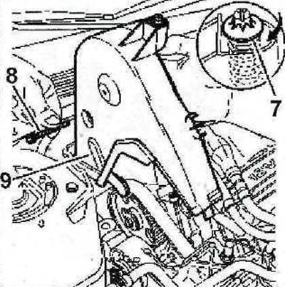
3.6 Turn bolt 7 ¼ turn, then unscrew bolt 8 and remove cover 9
7. Remove the front right wheel and fender liner.
8. Turn the crankshaft in the direction of the engine and align the hole on the camshaft gear, into which the thrust roller is inserted, with the hole on the rear cover of the timing mechanism.
9. Insert the thrust roller [1] into the corresponding hole and lock the crankshaft (see illustration).
![3.9 Insert the thrust roller [1] into the corresponding hole and lock the crankshaft](https://www.peugeotbook.ru/img/p600/0445.jpg)
3.9 Insert the thrust roller [1] into the corresponding hole and lock the crankshaft
10. Remove the intake manifold 10. Plug the opening of the pipe on the manifold to which the supply air duct is attached with a clean rag (see illustration).
[Original can be viewed at: Peugeotbook.ru]
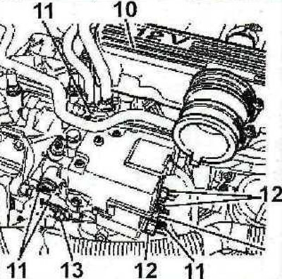
3.10 Remove the intake manifold 10
11. Unscrew the bolts 11 of the high-pressure fuel pump and disconnect the high-pressure fuel lines from the high-pressure fuel pump and fuel injectors by unscrewing the union nuts (see illustration 3.10).
12. Turn the high-pressure fuel pump all the way in the direction of the fuel supply delay and unscrew plug 13 (see illustration 3.10).
13. Insert the appropriate thrust roller [3] into the hole in which plug 13 was located (see illustration).
![3.13 Insert the appropriate thrust roller [3] into the hole in which plug 13 was located](https://www.peugeotbook.ru/img/p600/0447.jpg)
3.13 Insert the appropriate thrust roller [3] into the hole in which plug 13 was located
14. Slowly rotate the injection pump in the direction of fuel injection advance (to the engine compartment bulkhead), holding the thrust roller in the hole so that when aligned it enters the recess A (see illustration).
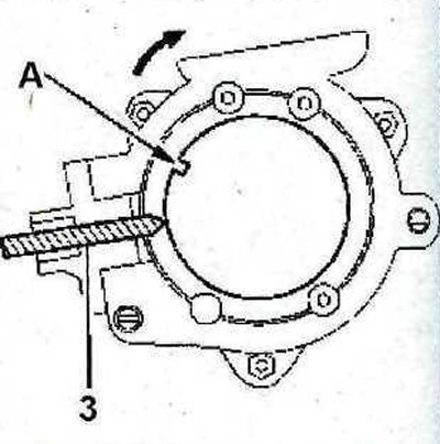
3.14 Slowly rotate the fuel injection pump in the direction of fuel injection advance so that the thrust roller enters the recess A when aligned
15. Holding the high-pressure fuel pump in this position, tighten bolts 11 and union nuts of the high-pressure fuel lines with a force of 20 Nm.
16. Remove thrust rollers 1 and 3, which were used to lock the crankshaft and fuel injection pump.
17. Turn the crankshaft in the direction of the engine and again align the hole on the camshaft gear for the thrust roller with the corresponding hole on the rear cover of the timing mechanism.
18. Lock the fuel injection pump with the thrust roller 3, slowly turning the crankshaft until the roller enters the recess A (see illustration 3.14).
19. Make sure that the injection pump is adjusted correctly by inserting the thrust roller 1 and locking the crankshaft (see illustration 3.9). If the injection pump is adjusted correctly, the thrust roller should fit into the corresponding holes without problems. Otherwise, the injection pump adjustment procedure should be repeated.
Cars with DK5ATE engine
20. Partially remove the timing belt and disconnect plugs 1 and 4 (see illustration),
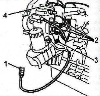
3.20 Partially remove the toothed belt and disconnect plugs 1 and 4
21. Disconnect the connectors from the high-pressure fuel pump, remove bracket 3 and disconnect the return and supply fuel lines (see illustration 3.20). Tightening torque of bracket bolts 25 Nm.
22. Unscrew bolts 5 and remove the fuel injection pump (see illustration). Tightening torque of bolts 20 Nm.
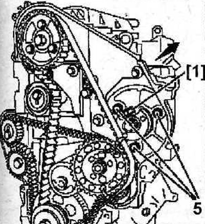
3.22 Unscrew bolts 5 and remove the fuel injection pump
The installation of the fuel injection pump is performed in the reverse order of removal.
Checking the fuel injection pump adjustment
23. Insert the thrust roller [1] (see illustration 3.22). If the roller is installed without problems, then the fuel injection pump is adjusted correctly.