



Table of contents: Engine speed adjustment (accelerator…🠇 Idle speed adjustment 🠇 Adjusting the fuel injection cycle…🠇 Correcting high idle speed 🠇
Bosch fuel injection pump adjustment is only possible on 1.9-liter XUD9TF engines. Since the fuel system on 2.1-liter engines is electronically regulated, it is recommended that adjustments in this case be left to a workshop.
On Bosch injection pumps installed on 1.9 liter XUD9TF engines, you can adjust the engine speed, idle speed, and the speed at which the engine stalls (engine stop), as well as increased idle speed.
Since no special tools are required to perform these adjustments, they can be performed independently. To perform adjustments, you will need a tachometer suitable for measurements on diesel engines. The procedure for making adjustments is as follows.
Engine speed adjustment (accelerator cable)
1. Depress the accelerator pedal fully.
2. Make sure that the idle speed lever 8 reaches all the way to the limit screw 9. As a rule, this is how it should be. Otherwise, move the accelerator cable housing mounting bracket "a" by one notch (groove) (see illustration).
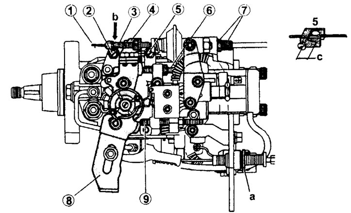
6.2 Adjusting the fuel injection pump
1 - High speed engine idle speed adjustment cable
2 - High speed idle speed adjusting screw
3 - coupling for fastening the idle speed adjustment cable at high engine speeds
4 - lock nut
5 - adjusting screw
6 - limit bolt
7 - mounting sleeve and lock nut of idle speed adjustment cable
8 - idle lever
9 - limit screw
a - accelerator cable housing mounting bracket
c - idle clearance
3. Warm up the engine to operating temperature. The radiator fan should turn on at least twice.
(View the original on the website: «PeugeotBook.ru»)
4. Make sure that the top of the lever 8 reaches the limit bolt 6 (see illustration 6.2). The idle speed control cable should not be tight at high engine speeds. This means that at point "c" the cable should have a play of 5-6 mm.
Idle speed adjustment
5. Start the engine and warm it up to operating temperature.
6. Check the idle speed. Loosen the lock nut of the limit bolt 6 and unscrew the bolt a few turns so that it does not touch the lever 8 (see illustration 6.2).
7. Adjust the idle speed with adjusting screw 5, bringing it to the nominal value and tighten the lock nut (see illustration 6.2). In Illustration 6.7, the idle speed adjusting screw is marked with the number 4.
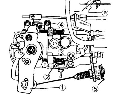
6.7 Adjusting the idle speed
1 - accelerator cable
2 - limit bolt
3 - limit bolt
4 - idle speed adjustment screw
5 - accelerator cable housing mounting bracket
Adjusting the fuel injection cycle reduction speed
8. Place a 3mm thick spacer washer or measuring template between lever 6 and stop bolt 7 (see illustration).
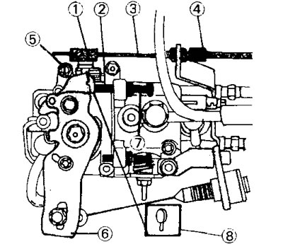
6.8 Adjusting the fuel cycle reduction speed
1 - cable fastening sleeve
2 - lever
3 - high speed engine idle speed adjustment cable
4 - idle speed adjustment cable mounting sleeve
5 - adjusting screw
6 - accelerator cable mounting lever
7 - limit bolt
8 - spacer washer or measuring template
9. Loosen the lock nut and turn the adjusting screw until the idle speed is 1500 rpm.
10. Tighten the lock nut and remove the spacer washer or measuring template.
Correcting high idle speed
11. Set lever 2 so that it rests against screw 5. If the idle speed is not within 950±50 rpm, then loosen the lock nut and turn screw 5 (see illustration 6.8).
12. Check the speed adjustment. If the engine is cold, then lever 2 should be adjacent to screw 5 (see illustration 6.8). If this is not the case, then adjust the tension of the high speed engine idle speed control cable using the I cable fastening coupling (see illustration 6.8). Accordingly, it will be necessary to move the installation sleeve 4 of the cable (see illustration 6.8).
13. Warm up the engine to operating temperature and make sure that the cable I on the end side of the fuel injection pump is not stretched (see illustration 6.2). The cable sag (play) should be 6 mm. If not, check the thermal switch on the coolant outlet pipe.