



Table of contents: Fuel filter and fuel heating unit 🠇 Exhaust gas recirculation system 🠇 Coolant temperature sensor 🠇 Exhaust gas recirculation solenoid…🠇 Mechanical exhaust gas recirculation…🠇 Fuel shut-off valve 🠇 Safety sensor 🠇 Fuel injectors 🠇 Preheating and support device 🠇 Glow plugs 🠇 Air filter 🠇 Exhaust gas recirculation system 🠇 Diesel fuel 🠇 Reducing exhaust toxicity 🠇
The 1.9-liter engine from the XUD9 family has been installed since approximately December 1994 and is equipped with a Bosch distributor-rotor fuel injection pump. The engines are equipped with an exhaust gas recirculation system. It is important to note that two engine types are installed: one without a catalytic converter and the other with an oxidation catalyst. Hence the corresponding letter designation of the engine (D8B-XUD9 TL/L without catalytic converter and DHX-XUD9 TF/Y with catalytic converter).
In early 1997, the installation of upgraded 1.9-liter engines, designated XUD9 BTF/W2 (D8B) and XUD9 BTF/L3, began. W2 denotes the exhaust gas emission level, which was brought into line with legal standards for passenger cars. XUD9 BTF/W2 engines do not have an EGR valve.
The XUD9 BTF/L3 engines are essentially the same XUD9 TF engine, but equipped with a Bosch VP20 fuel injection system, which works with an electronically controlled injection pump. The VP20 fuel injection system's electronic control unit regulates injection timing and fuel delivery, exhaust gas recirculation, and controls the preheat relay, altitude corrector, idle speed increase, air conditioning, engine speed sensor, and self-diagnostics system. This engine is equipped with a different gearbox from the others, designated ML5T.
The 2.1-liter engine of the XUD1 1 family is designated XUD11BTE/L3 (P8C) and is equipped with the EPIC fuel injection system developed by Lucas. The L3 also designates the exhaust gas emission level. The engine's new high-pressure fuel pump features fuel control valves, a fuel injection trim solenoid valve, a fuel shut-off valve, and various sensors, including a fuel temperature sensor, a camshaft position sensor, and a camshaft position sensor. The cylinder injectors have the same design, but differ in the shape of the body. The reason for this is the installation of a needle lift sensor on cylinder #4 injector. Like the 1.9-liter engine, this engine is also equipped with a turbocharger.
To dismantle the fuel injection pump on all types of engines, it is necessary to remove the toothed belt.
Please note: Since 1997, the fuel filter condensate level indicator light has not been installed on the instrument panel. In this regard, it is recommended to drain the condensate every 10,000 km.
The high-pressure fuel pump is located on the left side of the cylinder block and is driven by a timing belt. The electric fuel shut-off valve, installed on the high-pressure fuel pump, is designed to forcibly stop the fuel supply when the engine is turned off.
The fuel system of all engines consists of the following components: a fuel tank, a fuel heating unit, an air filter, a high-pressure fuel pump and four injectors.
Fuel filter and fuel heating unit
Fuel filtration and heating are integral functions of the fuel injection system. Fuel heating is achieved by coolant passing through the heating unit on the outlet pipe. The thermal valve installed on the heating unit regulates the volume of heated fuel. Fuel heating depends on the outside air temperature. When the air temperature drops below 15°C, the thermal valve opens, releasing channel "a" (see illustrations 1.0 and 1.0a).
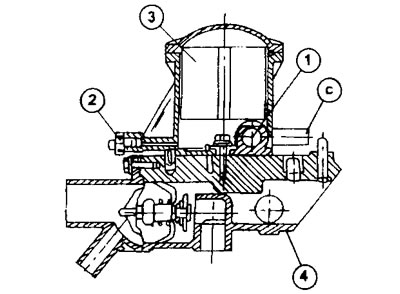
1.0 Fuel filter and fuel heating unit in section
1 - thermal valve
2 - ventilation plug
3 - fuel filter
4 - coolant outlet pipe
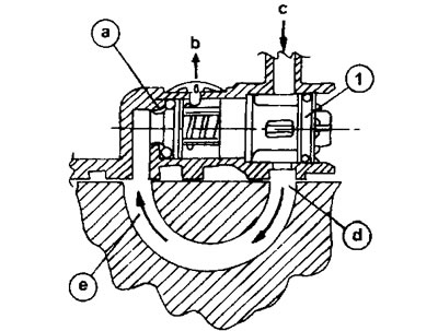
1.0a Fuel flow and heating diagram
a - thermal valve
c - inlet on the fuel heating unit
d - fuel circulation channel in the heating block, washed by hot coolant
e and b - outlet openings on the heating block leading to the fuel filter
At outside temperatures of 15-30°C, the thermostatic valve is only slightly open and only a small amount of fuel enters the heating unit. The main fuel flow is directed directly from "c" to "b".
The fuel circulation circuit is equipped with a ventilation valve that operates automatically.
Exhaust gas recirculation system
All engines are equipped with this system, regardless of whether a catalytic converter is installed or not. The exhaust gas recirculation system reduces harmful emissions into the atmosphere by directing part of the exhaust gas into the intake manifold (see illustration 1.0b).
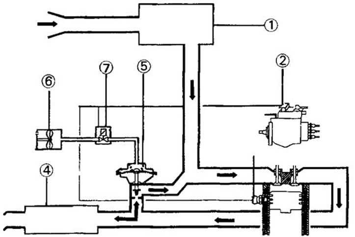
1.0b Exhaust Gas Recirculation System. 1.9-liter XUD9 engine with L3 emission standard
1 - air filter
2 - fuel injection pump load sensor
3 - thermal switch at 60°C
4 - exhaust system
5 - mechanical exhaust gas bleed valve
6 - vacuum pump
7 - electromagnetic valve of exhaust gas recirculation
EGR only occurs under certain conditions, depending on coolant temperature and engine load. The coolant temperature sensor in the outlet pipe sends a corresponding signal about the coolant temperature. Exhaust gas recirculation occurs when the engine temperature exceeds 60°C and the engine load does not exceed the nominal load value stored in the load sensor attached to the fuel injection pump. The control unit opens the EGR solenoid valve (7), which regulates the operation of the entire EGR system (see illustration 1.0b). In this case, the vacuum pressure generated by the vacuum pump located on the camshaft opens the mechanical exhaust gas bleed valve installed on the exhaust manifold, and part of the exhaust gas is diverted into the intake manifold.
When the engine is running at low speeds, the low pressure generated by the vacuum pump reaches its maximum. In this case, the mechanical exhaust gas diversion valve remains open, diverting exhaust gas into the intake manifold. The circulation of the exhaust gas is maintained by the pressure difference in the intake and exhaust manifolds, determined by the throttle valve, which is almost completely closed.
As the engine accelerates and its RPM increases, the low pressure generated by the vacuum pump drops and the mechanical EGR valve, under the action of a spring, gradually closes, reducing the volume of EGR directed into the intake manifold. At the same time, the throttle valve opens, letting in more fresh air.
Coolant temperature sensor
This sensor is located in the coolant outlet pipe and informs the electronic control unit about the coolant heating above 60°C, which is a signal to open the mechanical exhaust gas valve.
Exhaust gas recirculation solenoid valve
This valve is controlled by the electronic control unit and supplies low pressure to the mechanical exhaust gas bleed valve in the intake manifold.
Mechanical exhaust gas recirculation valve
The mechanical exhaust gas diversion valve is mounted on the exhaust manifold and is designed to regulate the volume of exhaust gas that is re-diverted to the intake manifold for subsequent afterburning. Under the influence of low pressure coming from the vacuum pump after the electronic control unit opens the electromagnetic valve of the exhaust gas recirculation to the membrane of the mechanical valve, the upper chamber of the mechanical valve opens. The valve is held in the closed position by a spring.
Fuel shut-off valve
The fuel injection system circuit includes an electromagnetic fuel shut-off valve that shuts off the fuel supply when the ignition is turned off.
Safety sensor
To improve passive safety, cars are equipped with a safety sensor (switch), triggered in the event of a sudden forced stop of the vehicle, as occurs during a collision, and which switches off the fuel pump. The switch is located in the engine compartment above the battery. The switch can be returned to its working position by pressing its button.
Fuel injectors
The fuel system is equipped with fuel injectors of different types. The injectors are color-coded for easy identification.
Preheating and support device
Preheating and maintenance operate the same on all engines, however some engine types are not equipped with this device. The regulator that controls the operation of the preheating and maintenance device is located on the partition below the battery. The regulator acts as a relay, from which power is supplied to the pre-heating plugs. Power is supplied to the glow plugs and the indicator light when the ignition is turned on if the coolant temperature is below 60°C. After a short time, the regulator cuts off power to the glow plugs. At the same time, during the engine start-up phase, power is supplied to the spark plugs and their glow continues for some time after start-up.
Pre-heating support means that the spark plugs remain in the glow phase even after the engine has started. Maintenance begins immediately after the engine is started and the starter is disconnected. During the first 15 seconds, the voltage supply to the glow plugs cannot be interrupted. After 15 seconds, the voltage supply may be cut off if the coolant temperature is above 60°C or if the accelerator pedal is in a certain position or is pressed beyond the programmed time.
Glow plugs
The type of glow plugs depends on the engine type. The relevant data are given in the specifications.
Air filter
The dry element air filter is located in the left side of the engine compartment on the inner side of the wing. The purpose of the air filter is the same for all engines, but the filter itself may differ in shape. When purchasing a new filter element, you must indicate the filter letter designation, engine number and year of manufacture.
The filter element should be replaced in accordance with the service manual (at a mileage of 60,000 km).
Exhaust gas recirculation system
All vehicles have an exhaust gas recirculation system, and an oxidation catalyst is installed only on certain models.
The exhaust gas recirculation system is designed to reduce nitrogen oxide emissions into the atmosphere. Part of the exhaust gases are re-circulated through the recirculation valve into the intake manifold. Since exhaust gases contain a minimal amount of combustible gases, re-intake of exhaust gases reduces the temperature in the combustion chambers, thereby reducing the formation of nitrogen oxides.
Diesel fuel
Diesel fuel consists of so-called paraffins. This hydrocarbon substance is flammable, but quickly crystallizes when the temperature drops. As a result, diesel fuel becomes paraffinized and is unable to pass through the fuel filter. Diesel fuel manufacturers solve this problem by adding so-called fuel flow improvers. These additives are not able to prevent fuel crystallization when the atmospheric temperature drops, but they do maintain its fluidity and the fuel can be supplied by the high-pressure fuel pump.
(Source available on the website PeugeotBook)
When refueling, it is recommended to use diesel fuel with a cetane number of 45. This type of diesel fuel is all-season.
Summer diesel fuel does not contain additives that improve flowability. This fuel paraffinizes at temperatures below -2°C.
There is also a so-called "transition" diesel fuel offered in the spring and fall. It can withstand temperatures below freezing, ranging from -8°C to -10°C
Winter diesel fuel contains improving additives and crystallizes at temperatures of -22°C.
If the car has not been used for a long time, it may happen that with the onset of cold weather it ends up filled with summer fuel. In this case, the problem can be solved with the help of an appropriate fuel improver additive offered at filling stations. Once you have selected the required type of additive, read the instructions for its use. After this, pour the contents, warmed to room temperature, into the fuel tank and refuel until the tank is full. Fuel at filling stations is stored in underground tanks and its temperature is sufficient for the additive to mix well with the fuel while driving.
This option is not possible if the summer fuel is paraffinized. In this case, the car should be placed in a heated garage to allow the fuel to become fluid again. And only after this can you use the appropriate additive.
Reducing exhaust toxicity
Certain types of engines are equipped with an oxidation catalyst (corresponds to an unregulated catalyst). The catalytic converter reduces hydrocarbon and oxide emissions by almost 50%. The catalytic converter is not a filter for carbon and soot, but it does help reduce their emissions. Typically, gaseous hydrocarbons are trapped by solid soot particles, thereby increasing their volume in the exhaust gas. However, when a catalytic converter is used, the hydrocarbons are oxidized and cannot come into contact with the soot or carbon particles.