



Table of contents: XUD Series Diesel Cars 🠇 Cars with DK5ATE engine 🠇
Injector malfunction manifests itself in:
- a) ignition failures;
- b) knocks in a cylinder or several cylinders;
- c) engine overheating;
- d) reduction of the effective engine power;
- d) the appearance of excessively black smoke from the exhaust pipe;
- e) increase in fuel consumption,
- g) the appearance of blue exhaust gases when starting a cold engine.
A faulty injector can be identified by loosening the union nuts securing the high-pressure fuel lines on each injector one by one. The engine should be idling. If, when loosening the fuel line nut on the next injector, the engine continues to run with the same noise or knocking, then this particular injector is faulty.
Checking the injectors for leaks and repairing them should be entrusted to a workshop. These works cannot be done independently, because they require special equipment. In addition, there is a risk of injury due to unprofessional performance of these works.
Depending on the type of engine fuel system, different types of injectors are installed.
The injector installed on the 4th cylinder has a needle stroke sensor designed to determine the start of fuel injection. The signal from this sensor goes to the electronic control unit of the injection system.
Attention! On DK5ATE engines, the injector of the 3rd cylinder is equipped with a needle stroke sensor.
Access to the injectors is difficult and therefore some parts must be removed to remove them. The injectors are located next to the glow plugs and protrude from the mount on the cylinder head (see illustration 2.0)
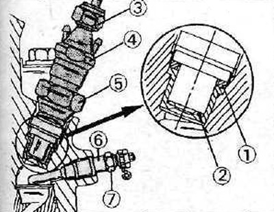
2.0 Fastening the injector to the engine
1 - copper ring
2 - heat-protective gasket
3 - union nut
4 - nozzle
5 - 27mm hex nut
6 - glow plug
7 - glow plug hex nut
XUD Series Diesel Cars
Removal
1. Disconnect the negative (-) battery terminal.
2. Unscrew the union nut of the high-pressure fuel line of the corresponding injector and move the fuel line to the side. To unscrew the union nuts, you can use a regular wrench, but do not allow the wrench to slip on the nut.
3. Disconnect the fuel return lines.
4. Unscrew the injector using a 27 mm socket head. Remove the copper sealing ring 2 of the injector and the heat-protective gasket 3 (see illustration).
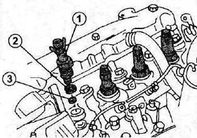
2.4 Unscrew the injector 1 using a 27 mm socket wrench
2 - copper sealing ring
3 - heat-protective gasket
Installation
The sequence of installing the injector is the reverse of removal.
5. Install a new sealing ring, heat shield and screw in the injector (see illustration).
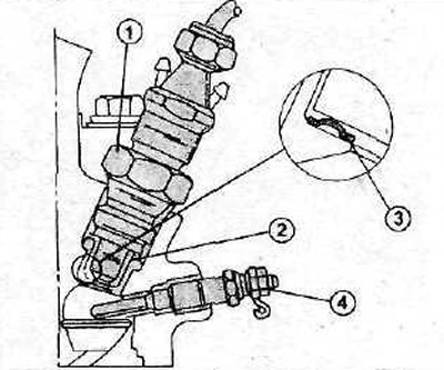
2.5 When installing the nozzle, the heat-protective pad must be placed with the convex side facing up
1 - nozzle
2 - copper sealing ring
3 - heat-protective gasket
4 - glow plug
6. Tighten the injector to a torque of 90 Nm. The union nuts of the fuel lines are tightened to a torque of 20 Nm. When tightening the union nuts, do not damage the hexagon of the nut.
Cars with DK5ATE engine
Removal
7. Disconnect the power steering line at points A and also the plugs 1 (see illustration).
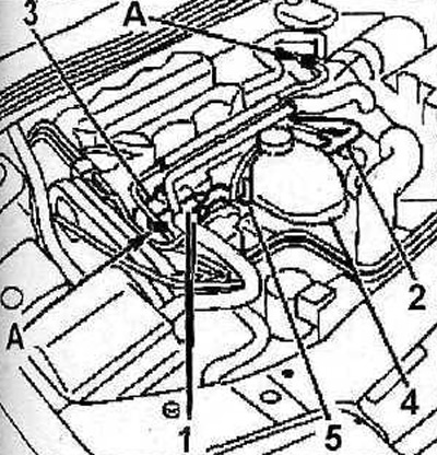
2.7 Disconnect the power steering line at point A
8. Remove bracket 3 and move aside the coolant expansion tank 4 together with its bracket 5 (see illustration 2.7).
9. Remove the holders 6 of the injectors, and then use the head [1] to unscrew the injectors themselves and remove the sealing gaskets 7 (see illustrations 2.9 and 2.9a). Sealing gaskets must be replaced with new ones when installing injectors.
![2.9 Using the head [1], unscrew the injectors and remove the sealing gaskets 7](https://www.peugeotbook.ru/img/p600/0441.jpg)
2.9 Using the head [1], unscrew the injectors and remove the sealing gaskets 7
6 - holder
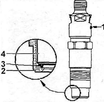
2.9a Fuel injector engine DK5ATE
7 - white color marking
2 - holder
3 - heat-protective gasket. Located inside the nozzle
4 - nozzle
Attention! When removing the third cylinder injector, do not damage the wire and plug 8 of the injector needle stroke sensor (see illustration 2.9).
[Data published on the website PeugeotBook]
The injectors are installed in the reverse order of their removal. The tightening torque of the injectors is 55 Nm.