



Table of contents: Cars with ES9ZJ4 engine 🠇 Cars with ZPJ series engines 🠇
Cars with ES9ZJ4 engine
1. Disconnect the negative (-) battery terminal from the battery.
2. Remove the protective cover 1 of the engine (see illustration).
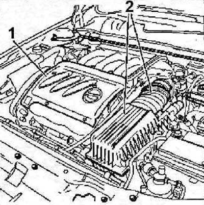
2.2 Remove the protective cover 1 of the engine
3. Remove the air filter and supply air duct 2 (see illustration 2.2).
[You can find the original on the page peugeotbook]
4. Move the accelerator cable 3 away from the work area (see illustration).
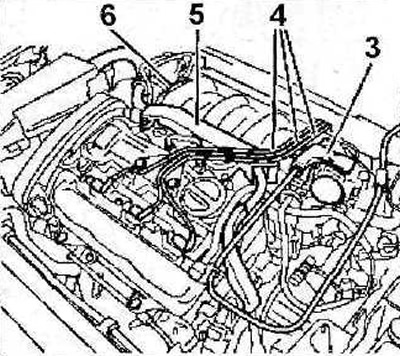
2.4 Move the accelerator cable 3 away from the work area
5. Disconnect the 4 high-voltage wire harness (see illustration 2.4).
6. Disconnect the engine wiring harness together with the holder (see illustration 2.4).
7. Disconnect hose 6 (see illustration 2.4).
8. Disconnect hose 6a, plugs 7, 8, 9,10 and 11, and then hose 12 (see illustration).
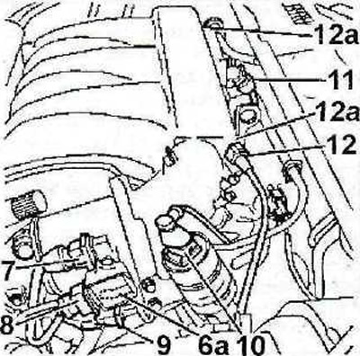
2.8 Disconnect hose 6a, plugs 7, 8, 9, 10 and 11, and then hose 12
9. Unscrew bolts 12a (see illustration 2.8). Tightening torque: 15 Nm.
10. Disconnect the cruise control switch unit (if provided).
11. Remove bracket 13 of the intake manifold (see illustration).
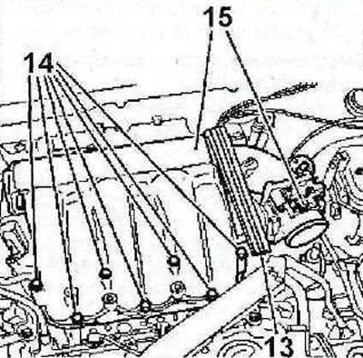
2.11 Remove bracket 13 of the intake manifold
12. Unscrew bolts 14 and remove the intake manifold together with the throttle valve 15 (see illustration 2.11).
13. Seal the inlet openings with suitable plugs.
Cars with ZPJ series engines
14. Disconnect the negative (-) battery terminal from the battery.
15. Disconnect the plugs and the supply air duct 1 from the throttle valve (see illustration).
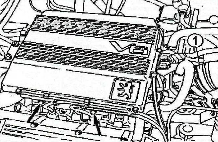
2.15 Disconnect the plugs and the supply air duct 1 from the throttle valve
16. Remove the engine protective cover.
17. Disconnect the low pressure hoses from the throttle valve and idle air control valve (see arrows in the illustration).
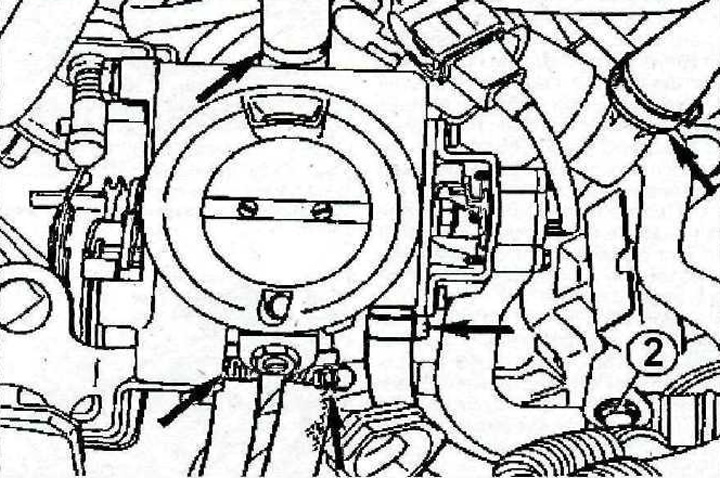
2.17 Disconnect the low pressure hoses from the throttle valve and idle air control valve (see arrows)
18. Disconnect the accelerator cable.
19. Unscrew bolt 2 (see illustration 2.17).
20. Disconnect and release the wire harnesses from the holders on the intake manifold.
21. Disconnect the connectors from the fuel pulsation reduction throttle valve.
22. Unscrew the 3 bolts securing the intake manifold and remove the manifold (see illustration).
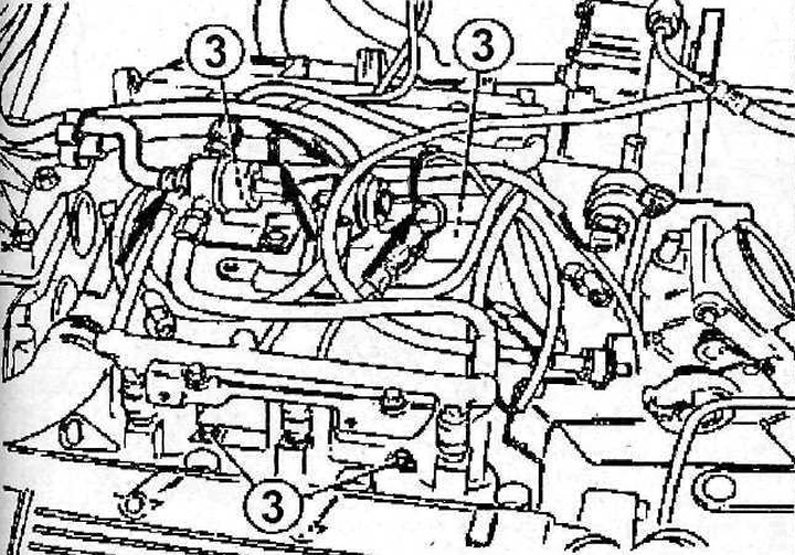
2.22 Unscrew the bolts 3 securing the intake manifold and remove the manifold