



Table of contents: Lucas high pressure fuel pump 🠇 Bosch high-pressure fuel pump 🠇
1. A conventional type tachometer, which works by reading the ignition system pulses, cannot be used on diesel engines. To make the following adjustments accurately, you will need to purchase or hire a suitable tachometer or have this work carried out by a Peugeot/Citroen dealer or other specialist with the appropriate equipment.
2. Warm up the engine to normal operating temperature before making adjustments. Make sure that the accelerator cable and high idle speed cable are properly adjusted as described in paragraphs respectively 11 and 4.
Lucas high pressure fuel pump
3. With the engine idling, position the adjusting shim to the correct thickness (see "Specifications") between the pump control handle and the anti-stall adjustment screw (figure 9.3).
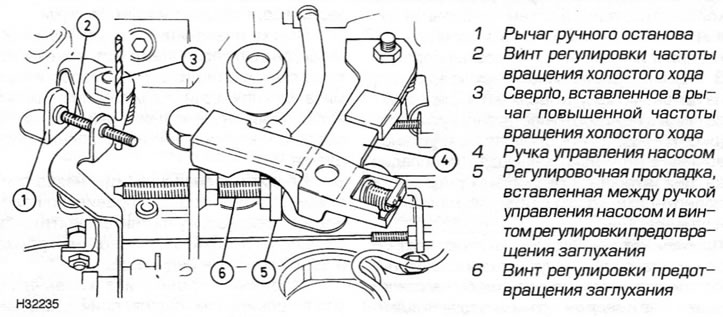
Figure 9.3. Lucas high pressure fuel pump adjustment
4. Push the manual stop lever all the way against the stopper and hold it in place by inserting a 9.0mm diameter rod/drill bit through the hole in the high idle speed lever.
5. The engine crankshaft speed must correspond to the specified value for the stall prevention speed.
6. If adjustment is necessary, loosen the lock nut, turn the anti-stall adjustment screw as required, and tighten the lock nut.
7. Remove the rod/drill, remove the adjusting shim and ensure that the engine is idling at the specified crankshaft speed.
8. If adjustment is necessary, loosen the lock nut on the idle speed adjustment screw. Turn the screw as required and tighten the lock nut.
9. Move the pump control handle to increase the engine speed to approximately 3000 rpm, then quickly release the lever. The deceleration should last for 2.5 to 3.5 seconds, and the engine speed should drop to approximately 50 rpm below idle speed.
10. If deceleration is too rapid and the engine stalls, turn the stall prevention adjustment screw a quarter turn toward the control handle. If the deceleration is too slow, causing insufficient engine braking, turn the screw a quarter turn away from the lever.
11. Tighten the lock nut after completing the adjustment. Check the idle speed of the crankshaft and adjust it if necessary as described above.
12. With the engine idling, check the operation of the manual stop control by turning the stop lever clockwise (figure 9.3). The engine must stop immediately.
13. If applicable, finally disconnect the tachometer.
14. After making all the adjustments described above, check the adjustment of the throttle position switch located on the pump control handle as described below.
15. Working with the end of the accelerator cable that is on the high pressure fuel pump side, place a mark on the cable 11.0 mm from the end of the cable sheath (figure 9.20).
16. Have an assistant depress the accelerator pedal until the mark on the cable is aligned with the edge of the cable sheath. When the cable is in this position, the contacts of the throttle position sensor-switch should barely open.
17. If adjustment is required, ensure that the mark on the cable is still aligned with the edge of the cable sheath, then loosen the screw securing the plastic actuator cam to the pump control handle (figure 9.17).
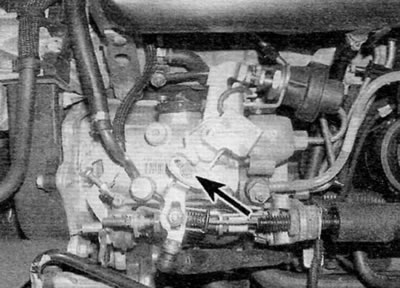
Figure 9.17. Fastening screw (marked with an arrow) actuating cam of the "throttle" position sensor-switch (lucas pump)
18. Move the actuator cam until the switch contacts open. Tighten the screw
19. Finally, disconnect the tachometer and, if applicable, install the engine cover.
Bosch high-pressure fuel pump
20. Loosen the lock nut and turn the anti-stall adjustment screw out enough to release the pump control handle (figure 9.20).
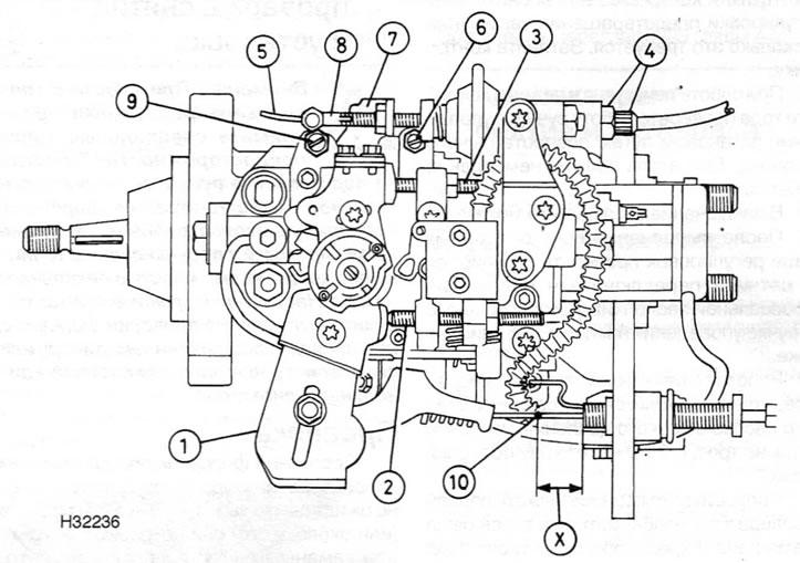
Figure 9.20. Adjusting the Bosch high-pressure fuel pump
1. Pump control handle
2. Maximum speed adjustment screw
3. Anti-stall adjustment screw
4. High idle speed cable adjustment screw and lock nut
5. High idle speed cable
6. Idle speed adjustment screw
7. High idle speed lever
8. High idle speed cable tip
9. High idle speed adjustment screw
10. Mark made on the accelerator cable for adjusting the throttle position sensor-switch X = 11.0 mm
21. Start the engine and let it idle. If the idle speed of the crankshaft is incorrect, release the lock nut and turn the idle speed adjustment screw as far as required, and then tighten the lock nut.
22. Insert an adjusting shim or feeler gauge of the proper thickness between the pump control handle and the anti-stall adjustment screw.
23. The crankshaft speed must correspond to the value set as the stall prevention speed.
24. If adjustment is necessary, loosen the lock nut and turn the anti-stall adjustment screw as required. Tighten the lock nut.
25. Remove the adjusting shim or feeler gauge and allow the engine to idle.
26. Move the high idle speed lever all the way to the end of the engine, where the flywheel is located, and make sure that the engine crankshaft speed increases to the set idle speed. If necessary, loosen the lock nut and turn the anti-fading adjustment screw as required. Tighten the lock nut.
27. With the engine idling, check the operation of the manual stop control by turning the stop lever. The engine must stop immediately.
28. Finally, disconnect the tachometer.
29. After making all the adjustments described above, check the adjustment of the throttle position switch located on the pump control handle as described below.
30. Working with the high pressure fuel pump end of the accelerator cable, place a mark on the cable 11.0 mm from the end of the cable sheath.
31. Have an assistant depress the accelerator pedal until the mark on the cable is aligned with the edge of the cable sheath. When the cable is in this position, the contacts of the throttle position sensor-switch should barely open.
32. If adjustment is required, ensure that the mark on the cable is still aligned with the edge of the cable housing, then loosen the two derailleur mounting screws.
33. Turn the switch housing until the contacts open and tighten the screws.