
Note. When installing the sensor, a new sealing washer must be used.
Removing
1. The thermostatic sensor is located on the side of the thermostat/fuel filter housing.
2. For easier access on 1.9L models, remove the air distribution housing as described in paragraph 3. If necessary, also remove the air intake duct and disconnect the vent hose from the oil filler pipe. For more information, please refer to the relevant paragraphs in this chapter.
3. Drain the coolant from the cooling system as described in chapter 1B.
4. Loosen the clamping screw or nut (whichever is applicable) and disconnect the high idle cable end from the cable on the fuel injection pump high idle lever (pic. 4.4, a, b).
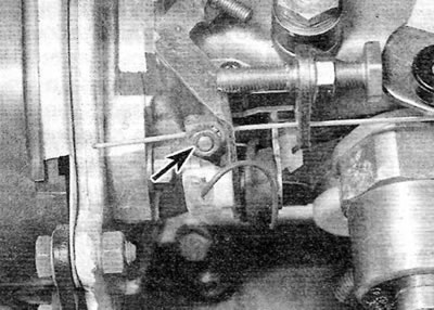
Pic. 4.4, a. Fast idle cable end clamp nut (marked with an arrow) (Lucas pump)
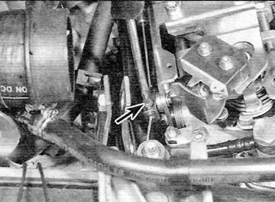
Pic. 4.4b. Loosening the fast idle cable clamp screw (marked with an arrow) (Bosch pump)
5. Remove the cable from the adjusting screw located in the bracket on the high pressure fuel pump (pic. 4.5).
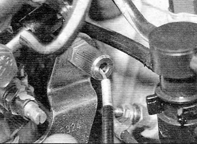
Pic. 4.5. Removing the high idle cable from the adjusting screw (Bosch pump)
6. Using a suitable open-end wrench, unscrew the thermostatic sensor from the thermostat/fuel filter housing and remove the sensor along with the cable (pic. 4.6). Remove the sealing washer, if applicable.
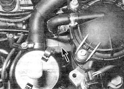
Pic. 4.6. High idle thermostatic sensor (marked with an arrow)
Installation
7. If a sealant was used for the original installation instead of a gasket, carefully remove all traces of «old» sealant from the sensor and housing. Make sure that no traces of sealant remain inside the coolant passages in the housing.
8. Install sensor using suitable sealant or new washer (whichever is applicable), and tighten it securely.
9. Insert the adjusting screw into the bracket on the high pressure fuel pump and tighten the locknut by hand.
10. Pass the cable through the high idle lever and install the lug on the cable, but do not tighten the clamp screw or nut (whichever is applicable).
11. Adjust the cable as described in the following paragraphs.
Adjustment
12. With the engine cold, fully push the high idle lever towards the flywheel end of the engine. Tighten the clamp screw or nut while keeping the tip of the cable in contact with the lever.
13. Adjust the screw so that the high idle lever touches the appropriate stop, and then tighten the locknut.
14. Measure the length of the exposed cable section.
15. Install the items removed to gain access to the sensor (see relevant paragraphs of this chapter).
16. Charge the cooling system as described in chapter 1B, and let the engine run until it reaches normal operating temperature.
17. Check that the high idle cable has slack. If not, the sensor may be defective.
18. With a hot engine, check if there is approximately 0.5-1 mm play in the cable on the Lucas pump, and 5-6 mm play on the Bosch pump. This indicates that the thermostatic sensor is working correctly.
19. Verify that the engine speed increases when the high idle lever is pushed towards the flywheel end of the engine. When the lever is pulled all the way to the limiter, the increased idle speed must correspond to the prescribed value (For details on adjusting the high idle speed, refer to paragraph 9).
20. Stop the engine.