
English Русский
Български
Беларускі
Український
Српски
Hrvatski
Română
Polski
Slovenský
Magyar
Bookmark Articles Sitemap Contacts
Company Hyundai Company Opel Company Skoda Company Kia Company Mitsubishi Company LADA Company Audi
PeugeotBook.ru


Series 100   Series 200   Series 300   400-500   Series 600   Crossovers   Others
 
Partner I (1996-2008) Peugeot 807 (2002-2014) Peugeot 806 (1994-2002) Peugeot J5 (1981-1993)

Fuel injection advance (Bosch high-pressure fuel pump) — checking and adjustment (Peugeot Partner I)

  • Main
  • Пежо
  • Partner I (1996-2008)
  • Power unit
  • Power and exhaust (XUD diesels)
  • Fuel injection advance (Bosch high-pressure fuel pump) — checking and adjustment
0
Warning. Do not attempt to perform injection advance adjustment procedures without accurate instruments. The appropriate special tools for adjusting the injection pump timing can be purchased at major auto parts stores or from your Peugeot/Citroen dealer. Before starting work, please read the safety precautions described in paragraph 1 this chapter.


Note: To check the injection advance of the high-pressure fuel pump, a dial indicator (Peugeot/Citroen special tool No. 3089-T) is required together with a special installation probe (Peugeot/Citroen special tool No. 5003-TD) and an adapter (Peugeot/Citroen special tool No. 7010-T). Without this equipment (or an appropriate alternative) the procedure for checking and adjusting the injection advance of the high-pressure fuel pump should be entrusted to a Peugeot/Citroen dealer or other specialist who has the appropriate equipment.


1. If the fuel injection advance is being checked without removing the pump from the engine, rather than during the pump installation procedure, disconnect the battery ground cable (see "Disconnecting the battery") and cover the generator with a clean cloth or plastic bag to protect it from possible fuel spills.

2. Remove the air intake duct between the air distribution housing and the air cleaner assembly as described in paragraph 3.

3. Remove the fuel injector lines as described in paragraph 5.

4. Disconnect the electrical connectors on the rear of the high pressure fuel pump.

5. Loosen the clamp screw and/or nut (whichever is applicable) and slide the high idle speed cable end along the cable so that it is no longer in contact with the high idle speed lever on the pump (that is, so that this lever returns to the limiter) (see paragraph 4).


6. Align the engine assembly/camshaft timing marks (see chapter 2B) to lock the crankshaft. Remove the crankshaft locking tool and then turn the crankshaft backwards (counterclockwise) approximately a quarter turn.

7. Unscrew the service plug located in the center between the four union nut connections of the injector lines on the back of the high-pressure fuel pump. After unscrewing the plug, place a suitable container under the pump to collect the leaking fuel. Wipe up any spilled fuel with a clean cloth.

8. Screw the adapter into the back of the pump and connect the dipstick to the dial indicator. Install the indicator and probe into the adapter (figure 8.8). If you do not have specific Peugeot/Citroen tools, suitable alternative tools can be purchased from many good auto parts stores. Position the indicator so that its plunger is at the mid-stroke and tighten the adapter locknut securely.
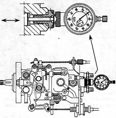
Figure 8.8. Dial indicator, adapter and installation probe for use on a Bosch pump

Figure 8.8. Dial indicator, adapter and installation probe for use on a Bosch pump


9. Slowly rotate the crankshaft in both directions, observing the dial indicator to determine when the high-pressure fuel pump piston reaches the bottom of its stroke (BDC). Once the piston is correctly positioned, reset the dial indicator to zero.


10. Slowly turn the crankshaft in the correct direction of rotation until the crankshaft locking tool can be reinstalled.

11. The reading on the dial gauge should be equal to the fuel pump injection advance value specified in "Specifications" at the beginning of this chapter. If adjustment is necessary, loosen the front and rear pump mounting nuts and bolts and slowly rotate the pump body until the point where the dial indicator reads the specified value is reached. Once the pump is properly positioned, tighten the front and rear nuts and bolts securely.

12. Turn the crankshaft 1% of a revolution in the normal direction of rotation. Determine the BDC position for the high pressure fuel pump piston as described in paragraph. 6, and reset the indicator to zero.

13. Slowly turn the crankshaft in the correct direction of rotation until the crankshaft locking tool can be reinstalled (to return the engine back to the TDC position). Check the injection advance again.

14. If adjustment is required, loosen the pump mounting nuts and bolts and repeat steps 11–13.

15. Having set the correct injection advance of the pump, unscrew the adapter and remove the dial indicator and dipstick.

16. Screw in the technological plug (with a sealing washer) into the pump and tighten it securely.

Source of the article is posted at (PeugeotBook)

17. If this procedure is performed as part of the pump installation sequence, proceed as described in paragraph 5.

18. If the procedure is performed without removing the pump from the engine, connect the fuel lines of the injectors, tightening their union nuts to the specified torque. Install the air intake duct. Connect the battery and then bleed the fuel system (see paragraph 2).

19. Start the engine and adjust the idle speed and stall prevention speed as described in paragraph 9. Also adjust the high idle speed cable as described in paragraph 4.
This article is available at russian, bulgarian, belarusian, ukrainian, serbian, croatian, romanian, polish, slovak, hungarian
Article reviewed by editor: Nikonova Veronica
Share information:
Previous
Partner I: Power and exhaust (XUD diesels)
Next

Fuel injection advance (Lucas high-pressure fuel pump) —…
Fuel injection advance — testing methods and adjustments
High-pressure fuel pump — removal and installation
High idle speed thermostat sensor
Air filter and related components — removal and installation
High pressure fuel pump — adjustment
Fuel injectors — inspection, removal and installation
Accelerator cable — removal, installation and adjustment
Fuel level indicator sensor — removal and installation
Collectors — removal and installation
See similar information for other Peugeot models

➨ Fuel injection system — testing and adjustment Peugeot 106 (1991-2003)
➨ Replacing the high pressure fuel pump (EP6DT engines) Peugeot 207 (2006-2014)
➨ Fuel injection pump (Bosch) — checking and adjusting injection… Peugeot 305 (1977-1989)
➨ Installation of high pressure fuel pump BOSCH Peugeot 405 (1987-1997)
➨ High pressure fuel pump — removal, installation and adjustment Peugeot 605 (1989-2000)
Link to this article in different formats
Comments and feedback from visitors
No comments yet


Add two numbers 35 + 41


Partner I (1996-2008) 
  • General information
  • Introduction to the guide
  • Faults en route
  • Weekly checks
  • User manual
  • Maintenance (petrol)
  • Maintenance (diesel)
  • Power unit
  • Petrol engines
  • Diesel engines «XUD»
  • Diesel engines «DW»
  • Overhaul of petrol engines
  • Overhaul of diesel engines
  • Cooling and heating
  • Power and exhaust (petrol)
  • Power and exhaust (XUD diesels)
  • Power and exhaust (DW diesels)
  • Emission reduction
  • Starting and charging system
  • Transmission
  • Clutch
  • Mechanical gearbox
  • Drive shafts
  • Chassis, running gear
  • Brake system
  • Car suspension
  • Steering
  • Body and interior
  • Exterior (external elements)
  • Interior (internal elements)
  • Doors, locks and windows
  • Electrical equipment
  • Equipment and devices
  • Electrical circuits
Peugeot 807 (2002-2014) 
  • General information
  • Operating instructions
  • Maintenance
  • Troubleshooting
  • Power unit
  • Gasoline engines
  • Diesel engines
  • Cooling and heating
  • Fuel injection (petrol)
  • Fuel system (diesel)
  • Fuel system
  • Exhaust system
  • Ignition system
  • Transmission
  • Clutch
  • Manual gearbox
  • Automatic gearbox
  • Chassis, running gear
  • Brake system
  • Car suspension
  • Steering system
  • Body and interior
  • Exterior (external elements)
  • Interior (internal elements)
  • Electrical equipment
  • Power devices
  • Electrical circuits
Peugeot 806 (1994-2002) 
  • General information
  • User manual
  • Maintenance
  • Power unit
  • Petrol engines
  • Diesel engines
  • Lubrication system
  • Cooling system
  • Fuel injection (petrol)
  • Fuel system (diesel)
  • Ignition and exhaust systems
  • ECM Bosch Motronic MP 3.2
  • ECM Magneti-Marelli (MM)
  • Transmission
  • Clutch
  • Mechanical gearbox
  • Chassis, running gear
  • Brake system
  • Car suspension
  • Steering
  • Electrical equipment
  • Equipment and devices
  • Electrical circuits
Peugeot J5 (1981-1993) 
  • General information
  • Introduction to manual
  • Specifications
  • Gasoline engine
  • Engine repair
  • Lubrication system
  • Cooling system
  • Fuel system
  • Ignition system
  • Diesel engine
  • Engine repair (DB9)
  • Lubrication system (DB9)
  • Cooling system (DB9)
  • Fuel injection (DB9)
  • Engine repair (U25)
  • Lubrication system (U25)
  • Cooling system (U25)
  • Fuel injection (U25)
  • Transmission
  • Clutch
  • Gearbox
  • Drive shafts
  • Chassis, running gear
  • Steering system
  • Car suspension
  • Brake system
  • Electrical equipment
  • Power devices
  • Electrical circuits
PeugeotBook.ru © 2018–2026 | Mobile version | Sitemap: EN BG BY UA RS HR RO PL SK HU | Write message | Site search | Add to bookmarks | Peugeot owners
106 (1991-2003) | 206 (1998-2012) | 207 (2006-2014) | 305 (1977-1989) | 306 (1993-2002) | 307 (2001-2008) | 405 (1987-1997) | 406 (1995-2004) | 605 (1989-2000) | Partner-I (1996-2008) | Eurovans-807 (2002-2014) | Eurovans-806 (1994-2002) | J5 (1981-1993) |
Cookies are used to ensure the correct display of pages on the site.