Table of contents: Bosch fuel injection pump on 405…🠇 Bosch fuel injection pump on 405…🠇 Fuel injection pump (405 models with…🠇 Fuel injection pump (all models) -…🠇
Please note: Some of the pump adjustment screws and inspection plugs may be sealed during factory assembly. If the car is still under warranty, these seals cannot be removed. Do not attempt to adjust the pump timing unless you have sufficiently accurate measuring instruments.
1. Disconnect the negative cable from the battery.
2. Cover the generator with a plastic bag to protect it from fuel splashes.
3. Apply the handbrake and jack up the front right wheel of the car until it is off the ground. Support the car and engage 4th or 5th gear. This will allow the engine to be turned using the right front wheel.
4. Disconnect the wire from the glow plug of cylinder No. 4 (from the timing belt side) and unscrew the spark plug. Keep in mind that the injection timing is adjusted with piston No. 4 in the TDC position on the compression stroke (i.e. piston No. 1 is at 8 TDC with the valves changing their position).
5. You will need two dial gauges to check the position of piston No. 4 and the fuel injection pump. You will also need magnetic stands or brackets to mount the gauges in the correct locations on the engine.
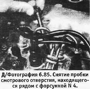
6. Unscrew and remove the plug on the cylinder head next to injector No. 4.
7. Turn the engine forward until pressure is felt in cylinder No. 4, indicating that piston No. 4 has begun to rise on the compression stroke.
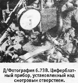
8. Place the dial gauge over the inspection hole and apply its probe to the piston.
 |
 |
9. Turn the engine forward again until the instrument shows the maximum lift of piston No. 4. To check, turn the engine slightly forward and backward until the piston reaches the top position, and set the instrument to zero.
10. Unscrew the nuts of the fittings and disconnect the fuel pipes of injectors NN 1 and 2 from the high-pressure fuel pump.
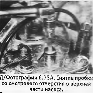
11. Unscrew the inspection hole plug on the end of the high-pressure fuel pump (between the fuel pipes of the injectors). Be prepared for some fuel to spill when doing this.
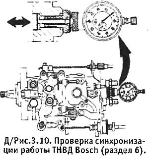
12. Insert the probe and connect it to the dial gauge positioned directly above the hole. The device used in Peugeot workshops is shown in Figure 3.10.
13. Turn the engine back approximately 1/8 of a turn or until piston No. 4 moves 4.0 mm down the cylinder.
14. Set the dial gauge located on the high-pressure fuel pump to zero.
15. Slowly turn the engine forward until the dial gauge on the high-pressure fuel pump shows 0.30 mm and then check that the upper dial gauge shows 0.80 ± 0.03 mm BTDC for models with a 1.7 L engine or 0.50 ± 0.03 mm BTDC for models with a 1.9 L engine. If other readings are obtained, do the following.
16. Check the accuracy of the upper dial instrument zero setting by repeating the procedure specified in paragraph 9.
17. Turn the engine back approximately 1/8 of a turn or until piston No. 4 moves 4.0 mm down the cylinder. Now slowly turn it forward until the upper dial gauge shows 0.80±0.03 mm BTDC for models with a 1.7 L engine or 0.50±0.03 mm BTDC for models with a 1.9 L engine.
18. Unscrew the nuts of the fittings and disconnect the fuel injector pipes from the high-pressure fuel pump. Loosen the fuel injection pump mounting nuts and bolts.
19. Turn the pump body counterclockwise (if you look from the side of the fuel injector pipes) and set the dial gauge to zero. Slowly turn the pump clockwise until the dial gauge shows 0.30 mm.
20. Tighten the pump mounting nuts and bolts, ensuring that the dial gauge does not show any movement.
21. Check the pump synchronization again as described in paragraphs 13-15.
22. Remove the dial gauges and replace the plugs. Connect the fuel pipes to the injectors and tighten the fitting nuts.
23. Install the glow plug in place and connect the wire to it.
24. Lower the car to the ground and connect the negative cable to the battery. Remove the plastic bag from the generator.
25. Pump fuel into the system (see section 17).
Bosch fuel injection pump on 405 models
1. Read the warning at the beginning of this section and follow the instructions in paragraphs 1-4 (see above). If desired, you can leave the spark plug in place and instead unscrew and remove the inspection hole plug located next to injector No. 4 (see photo).
2. Remove the intermediate radiator (on models with a turbo engine) or air distribution box (on models with a non-turbocharged engine).
Source of the article is website: PeugeotBook.ru
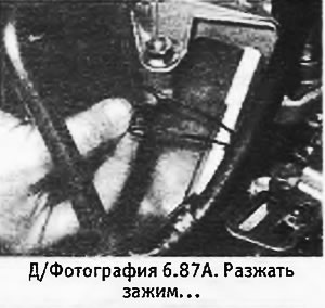
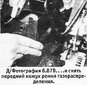
3. Release the clamps and remove the front timing belt cover (see photos).
 |
 |
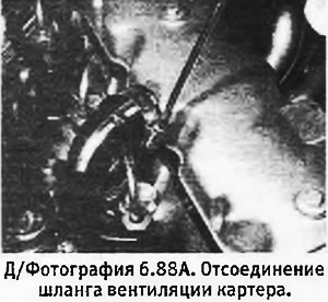
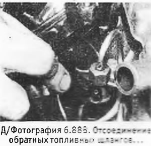
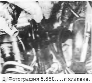
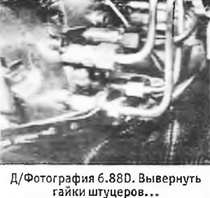
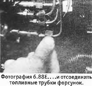
4. Note the position of the fuel injector pipes, unscrew the fitting nuts and disconnect the pipes from the high-pressure fuel pump and injectors (this is done to ensure freedom of movement of the fuel injection pump). Be prepared for some fuel to spill when disconnecting the lines. To create more room to work, disconnect the crankcase ventilation hose from the valve cover. Also disconnect the return fuel hoses and valve. Plug the resulting holes to prevent dirt from entering the system (see photos).
 |
 |
 |
 |
 |
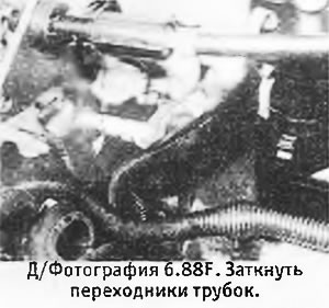 |
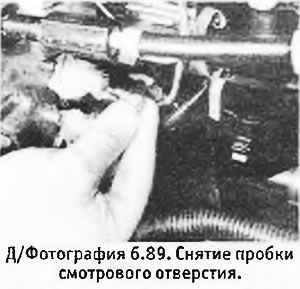
5. Unscrew the plug on the end of the fuel injection pump (between the fuel pipes of the injectors) photograph).
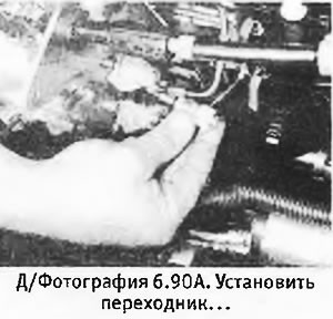
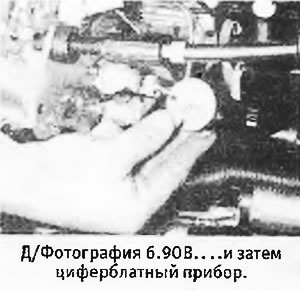
6. Install the dial gauge onto the end of the fuel injection pump through the adapter until it reads 2-3 mm. Depending on the size of the dial gauge, it may be helpful to remove the oil separator and secure it to the side with a plastic tie.
 |
 |
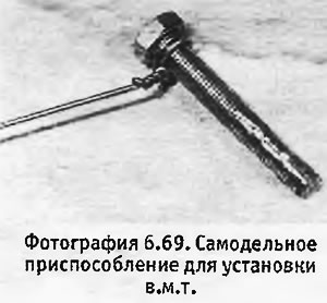
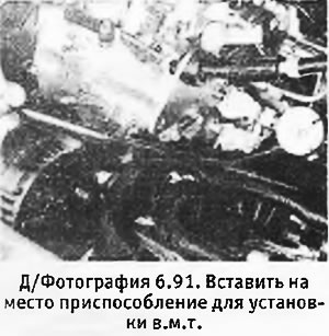
7. Turn the engine forward until pressure begins to be felt in cylinder No. 4, indicating that piston No. 4 has begun to rise on the compression stroke. Continue to rotate the engine in its normal direction of rotation until it is possible to insert an 8 mm rod into the mounting hole so that it enters the flywheel. At this moment, piston N4 will reach TDC on the compression stroke. It is recommended that the rod be bent so that it can pass behind the starter (see photo). Alternatively, you can use a homemade device like the one used to adjust the Lucas CAV/Roto-Diesel fuel injection pump (see photo 6.69).
 |
 |
8. Remove the TDC setting tool and turn the crankshaft counterclockwise until the injection pump plunger is at BDC (the dial gauge readings should stop decreasing). In this position, set the device to zero.
9. Slowly turn the crankshaft in the normal direction of its rotation so that piston No. 4 reaches the TDC position and the TDC setting device can be inserted into the flywheel.
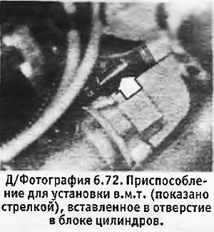
10. Check that the dial gauge readings correspond to the value indicated in Specifications for static synchronization of the pump on the engine of the required brand.
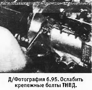
11. If adjustment is necessary, loosen the fuel injection pump mounting bolts and turn the pump body all the way away from the engine (see photo).
12. Slowly turn the pump body in the opposite direction (towards the engine) so that the dial gauge shows the correct value for static synchronization.
13. Tighten the pump mounting bolts to the specified torque and check the pump synchronization again.
14. Remove the TDC setting tool and dial gauge.
15. Install the plug on the end of the fuel injection pump and tighten it securely.
16. Install the fuel injector pipes in place and tighten the fitting nuts.
17. Install the front timing belt cover.
18. Install the air distribution box (engines without turbocharging) or intermediate radiator (models with turbo engines).
19. Replace and tighten the inspection hole plug or glow plug (depending on what was being filmed).
20. Remove the plastic bag from the generator and connect the negative cable to the battery.
21. Lower the car to the ground.
Bosch fuel injection pump on 405 models
1. Mark the gas pedal cable 11.0 mm from the end of the braid (see photo).
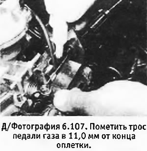
2. Move the load lever so that the mark on the cable aligns with the end of the sheath, and hold it in this position.
3. Loosen the switch mounting screws and turn it until a click is heard, indicating that the internal contacts have opened (see photo).

4. With the switch in this position, tighten the mounting screws and then release the lever.
5. Move the lever again and check that the switch contacts are triggered at the moment when the mark on the cable coincides with the end of the braid.
Fuel injection pump (405 models with XUD9 engine) - description
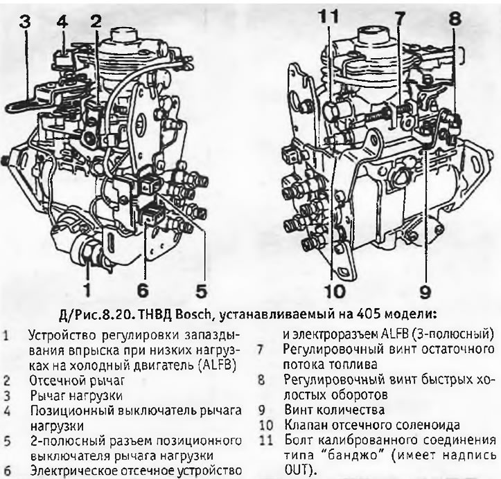
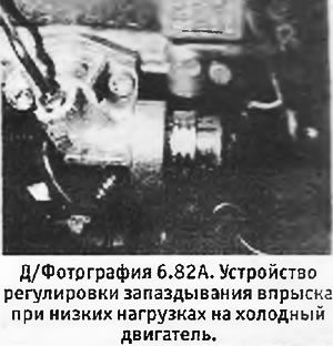
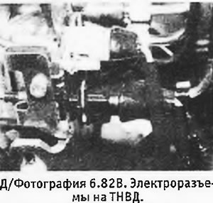
1. As follows from Specifications, The models in question may be equipped with either Lucas or Bosch fuel injection pumps. Figure 8.20 shows a Bosch fuel injection pump (see photos).
Fuel injection pump (all models) - dynamic regulation of injection timing
1. The setting values for dynamic regulation of the fuel injection pump on some models are indicated in Specifications. However, dynamic regulation itself requires the use of expensive equipment, which is usually not available in a home workshop. The adjustment procedure varies depending on the type of equipment used, so the manufacturer's instructions should be strictly followed in each specific case. Keep in mind that most dynamic testers provide readings to within ±2°.
2. Dynamic control must be carried out within the limitations dictated by the equipment used. If the results of dynamic regulation appear unsatisfactory, the matter can only be corrected by static regulation of the pump.
 |
 |