
2. Cover the generator with a plastic bag so that fuel does not get on it.
3. Remove the air cleaner with air channels (see section 3).
4. Where necessary, disconnect the crankcase ventilation hoses and remove the oil separator.
5. Engage the handbrake and jack up the right front wheel of the vehicle until it is off the ground. Support the car and engage 4th or 5th gear. This will allow the engine to be turned by turning the right front wheel.
6. Pull up the special clip, loosen the spring clips and remove the front section of the timing belt cover.
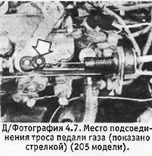
7. Move the feed lever to the injection pump to the open position and disconnect the cable by passing it through a special slot (see photo). Disconnect the cable adjustment ring from the bracket.
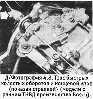
8. Pay attention to the position of the end stop on the fast idle cable, loosen the screw and disconnect the cable (see photo). Unscrew the adjusting locknut and remove the cable with the adjusting ring from the bracket.
9. Loosen the clamp and disconnect the fuel supply hose.
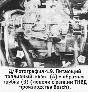
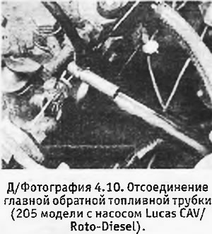
10. Disconnect the main fuel return pipe and the injector bypass return pipe from the nozzle tube.
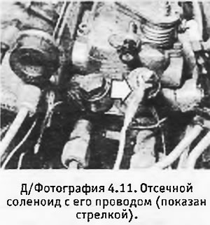
11. Disconnect wiring from shutoff solenoid.
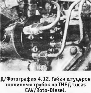
12. Unscrew the nuts of the fittings that secure the fuel pipes of the injectors to the injection pump (see photo) and the injectors themselves. Remove tube assembly.
13. Turn the engine using the right front wheel so that the two bolt holes in the injection pump sprocket align with the corresponding holes in the engine front plate.
14. Insert 2 M8 bolts into aligned holes and hand tighten. Please note that the bolts must hold the sprocket during the removal of the injection pump, which eliminates the need to remove the timing belt.
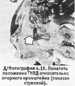
15. Mark the position of the injection pump relative to the support bracket (see photo), which will allow you to install it in its original position during assembly. When installing a new pump, transfer the mark from the old pump to it to approximate the pump in the desired position.
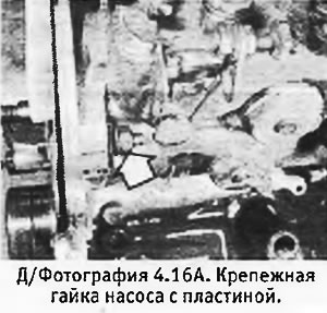
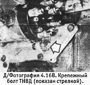
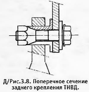
16. Turn out 3 fixing nuts and to remove plates. Unscrew and remove the rear mounting bolt and support the injection pump with a wooden block (see pictures).
 |  |
17. Unscrew the sprocket nut so that the shaft cone comes out of the sprocket. Together with the plate bolted to the sprocket, the nut acts as a puller.
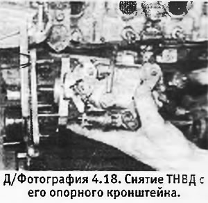
18. Unscrew the sprocket nut and remove the injection pump from its support bracket (see photo). Remove the key if it falls out of the groove on the shaft.
19. Start pump installation by installing segmented key (if she filmed) into a groove in the shaft.
20. Remove the bolts securing the puller plate to the injection pump sprocket.
21. Insert the injection pump into place in the sprocket, checking that the shaft key is in the groove on the sprocket. Screw the nut back in place and tighten it by hand.
22. Install the fixing nuts with their plates and tighten them by hand.
23. Tighten the sprocket nut to the correct torque, then install the puller plate and tighten the bolts.
24. Unscrew 2 bolts and remove them from the injection pump sprocket.
25. If you did not replace the injection pump, align the marks made and tighten the fixing nuts. When installing a new pump, adjust the valve timing (see section 5 or section 6).
26. Connect the fuel pipes to the injection pump and nozzles and tighten the union nuts.
28. Connect the wire to the shut-off solenoid.
29. Install the supply and return fuel pipes.
30. Install the fast idle cable and gas pedal cable and adjust them in accordance with sections 7 and 8.
31. Install the sections of the casing of the timing belt and secure them with spring clips.
32. Lower the machine to the ground and turn off the handbrake.
33. Remove the plastic bag from the generator and connect the negative wire to the battery.
34. Where applicable, install oil separator and crankcase breather hoses.
35. Install an air cleaner with air channels.
36. To priming fuel, turn on the ignition to energize the shut-off solenoid, and then operate the manual priming pump on the fuel filter until resistance is felt. On early models with a Lusas CAV/Roto-Diesel filter, first unscrew the manual primer pump plunger and then tighten it again when primer is finished.
37. Turn the ignition key to position "M" and wait until the preheat signal lamp goes out. Start engine and adjust idle (see section 9).
Injection pump (turbo engine models) - description
1. The injection pump installed on the turbo model is similar to that used on non-turbo engines, but with some additional features.
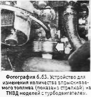
2. A special device varies the amount of fuel injected depending on the turbo boost pressure. The pressure value is read through a hose connected to the intake manifold (see photo).
3. The electromagnetic timing system makes the injection earlier on a cold engine. This system is deactivated by a contact actuated by the fast idle lever (see pictures).
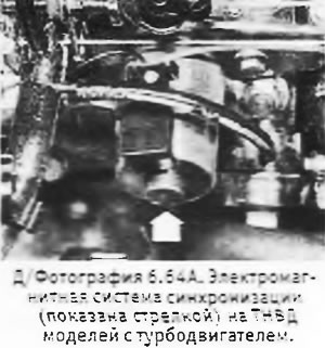 | 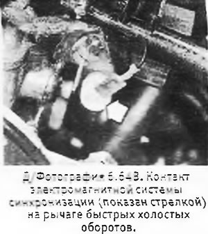 |
4. All these additional devices can only be checked and adjusted by a specialist.
Injection pump (turbo engine models) - removal and installation
5. Follow the instructions given earlier, additionally disconnecting the boost pressure hose from the device for changing the amount of injected fuel.
6. The injection pump is installed in the reverse order. If necessary, check pump timing as described below.