
Warning. Be careful when performing this procedure to ensure that no dirt enters the high pressure fuel pump or fuel injector lines. When installed on fittings of the type «banjo» fuel lines, use new O-rings.
Removing
1. Disconnect the ground wire from the battery (see «Disconnecting the battery»).
2. Cover the generator with a plastic bag as a precaution in case of diesel leakage.
3. For easier access on 1.9L models, remove the air distribution housing as described in paragraph 3. If necessary, also remove the intake air duct and disconnect the vent hose from the oil filler pipe. For more information, please refer to the relevant paragraphs in this chapter.
4. Chock the rear wheels and release the parking brake. Raise the right front corner of the car to free up the wheel. Install secure stands under the car (see «Lifting and placing the car on supports») and engage 4th or 5th gear. This will ensure that the engine can be easily turned by the right wheel.
5. Remove the upper timing belt covers (see chapter 2B).
6. If necessary, disconnect the hoses from the vacuum converter at the end of the high pressure fuel pump.
7. Disconnect the accelerator cable from the high pressure fuel pump (see paragraph 11).
8. Disconnect the high idle cable from the high pressure fuel pump (see paragraph 4).
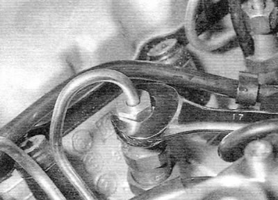
9. Release the clamp or disconnect the union type «banjo» (with hollow screw) and disconnect the fuel supply hose. Remove the sealing washers from the union type «banjo» (if applicable). Plug the open end of the hose and screw in and close the union bolt to prevent dirt from entering (pic. 5.9, a, b).
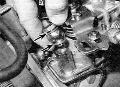
Pic. 5.9, a. Disconnection spigot type «banjo» fuel supply line to the fuel pump. Pay attention to sealing washers (marked with arrows) (Bosch pump)
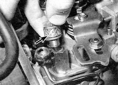
Pic. 5.9b. Bolt installation of spigot type «banjo» fuel supply line with a small piece of fuel hose (marked with an arrow) to prevent the ingress of dirt (Bosch pump)
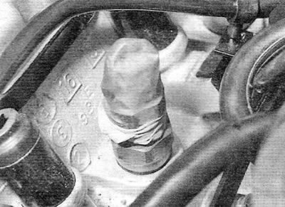
10. Disconnect the main fuel return line and disconnect the union type «banjo» injector fuel return line (pic. 5.10). Remove the sealing washers from the union type «banjo». To prevent dirt from entering, plug the open end of the hose and close the fitting bolt type «banjo». Take care not to confuse the inlet and outlet connections of the union type «banjo».
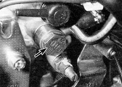
Pic. 5.10. Union type «banjo» high pressure fuel pump return line (marked with an arrow) (Bosch pump)
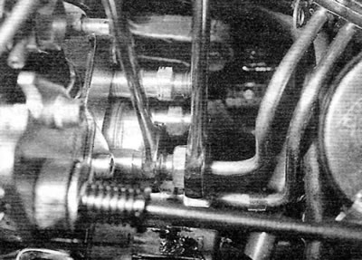
11 Disconnect all relevant electrical wiring from the pump. Be aware that on some Bosch pumps this can be done by simply unplugging the electrical connectors in the brackets on the pump (pic. 5.11). On some pumps, it will be necessary to disconnect the electrical wiring from various elements (some connections can be protected with rubber caps).
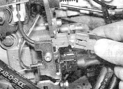
Pic. 5.11. Disconnection of an electric socket of the fuel pump of a high pressure (Bosch pump)
12. Turn away union nuts of fastening of pipelines of atomizers to the fuel pump of a high pressure and atomizers. Hold the fittings on the pump when unscrewing the union nuts securing the pipelines to the pump. Remove the pipelines as a single set. Plug open ports to prevent dirt from entering. To do this, you can use small plastic bags or «fingers», cut off from «old» (but clean!) rubber gloves (pic. 5.12, a-d).
Pic. 5.12, a. Disconnection of the union connection of the fuel line on the nozzle
Pic. 5.12 b. Close the open end of the nozzle to prevent dirt from entering
Pic. 5.12, c. Loosening the fuel line union at the pump (Bosch pump)
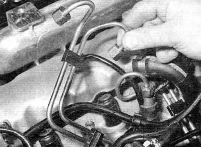
Pic. 5.12, d. Removing the fuel line kit
13. Rotate the crankshaft until the two bolt holes in the high pressure fuel pump sprocket are aligned with the corresponding holes in the engine front plate.
14. Insert two M8 bolts through the holes and hand tighten. Keep in mind that these bolts should support the toothed pulley while the high pressure fuel pump is removed, thus eliminating the need to remove the timing belt (pic. 5.14).
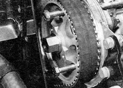
Pic. 5.14. Bolts inserted through the mounting holes in the high pressure fuel pump sprocket
15. Using a scriber or marker, mark the position of the high pressure fuel pump relative to the support bracket (pic. 5.15). This will ensure that the correct injection timing of the pump is maintained during installation.
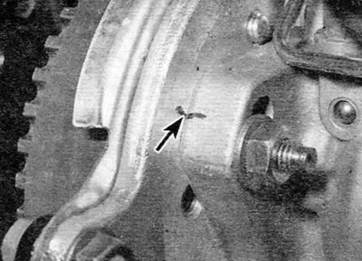
Pic. 5.15. Mark the position of the high pressure fuel pump relative to the support bracket (marked with an arrow)
16. Turn away three forward nuts of fastening of the pump and remove washers. Unscrew the rear nut and remove the bolt, noting for yourself the location of the washers (pic. 5.16, a, b). Place a block of wood under the high pressure fuel pump.
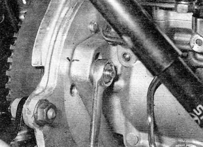
Pic. 5.16 a. Unscrewing the front nut of the high pressure fuel pump (Bosch pump)
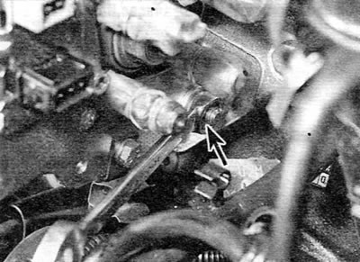
Pic. 5.16b. Unscrewing the rear nut of the high pressure fuel pump (marked with an arrow) (Bosch pump)
17. Remove the fuel pump sprocket from the pump shaft as described in Chapter 28. Note that the sprocket can be left engaged with the timing belt while the pump is removed from its appropriate support bracket. Screw in the M8 bolts to keep the toothed pulley in place while the pump is removed.
18. Carefully remove the pump. Remove the key from the groove on the pump shaft if it is not secured. Remove the bushing from the back of the support bracket.
Installation
19. Begin installation of the high pressure fuel pump by inserting the segment key into the groove on the pump shaft (if it was taken out).
20. Move the pump to the support bracket and place a wooden block under it, as in the case of removal.
21. Insert the pump shaft into the toothed pulley and install the toothed pulley as described in chapter 2B. Make sure that the segment key does not fall out of the groove on the shaft when installing the toothed pulley.
22. Align the marks made on the pump and support bracket before removing the pump. If a new pump is being installed, transfer the marks from «old» pump with a new one to provide an approximate pump setting.
23. Screw on the nuts / screw the pump mounting bolt and tighten them slightly (whichever is applicable).
24. Adjust fuel injection advance as described in paragraphs 6, 7 and 8 (whichever is applicable).
25. Install and connect fuel injector lines.
26. Connect all appropriate electrical wiring to the pump.
27. Connect the supply and return fuel hoses and tighten the appropriate connections. On fittings of the type «banjo» use new sealing washers.
28. Connect the high idle cable and adjust it as described in paragraph 4.
29. Connect and adjust the accelerator cable (see paragraph 11).
30. If necessary, connect the hoses to the vacuum converter.
31. Install the upper timing belt covers.
32. Lower the car.
33. If applicable, install the air distribution housing, air intake duct and vent hose.
34. Remove the plastic bag covering the generator.
35. Connect the wire «masses» to the battery.
36. Bleed the air from the fuel system as described in paragraph 2.
37. Start the engine and check the high pressure fuel pump settings as described in paragraph 9.